This thread has been locked.

If you have a related question, please click the "Ask a related question" button in the top right corner. The newly created question will be automatically linked to this question.

MCF8329EVM: MPET not working

Part Number: MCF8329EVM
Other Parts Discussed in Thread: MOTORSTUDIO, , MCF8316A, MCF8329A

I am trying to get a MCF8329AEVM working with a small 100W 10 pole motor running at 36V.  Running the board standalone, the motor spins nicely, with speed controlled well using the pot.  However, when I run Motor Studio, MPET fails.  The motor never moves at all nor makes any clicks.  I get the following in the log:

1:42:10:338 | : Could not detect any MPET fault. Please check the tuning file..

1:36:57:483 | :Beginning Motor Ke measurement...(Your motor will spin up slowly during this time)

1:36:54:474 | : Adjusting MPET_OPEN_LOOP_SLEW_RATE and retrying MPET

1:31:41:723 | :Beginning Motor Ke measurement...(Your motor will spin up slowly during this time)

1:31:38:706 | : Adjusting MPET_OPEN_LOOP_CURRENT_REF and retrying MPET

1:31:38:695 | : MPET BEMF Fault detected!!

1:31:38:672 | :Beginning Motor Ke measurement...(Your motor will spin up slowly during this time)

1:31:38:666 | : Motor ke measurement error...checking for faults.

1:30:30:539 | :Beginning Motor Ke measurement...(Your motor will spin up slowly during this time)

1:30:26:501 | : Running MPET...

1:30:22:917 | : Default register settings loaded.

Any suggestions?

  • Hi Marc, 

    Thanks for your post to the e2e motor drivers forum.

    Many of our team members are currently out of office for US holiday timeframe - but will be back in office by 1st week of January.

    Please anticipate a delayed response & feel free to provide additional information in the meantime.
    Best Regards,
    Andrew

  • I am still looking for an answer for the above.  Plus I have new questions:

    1) At some point I tried saving updated parameters to the EEPROM.  This has caused the eval board to no longer spin the motor in standalone mode (which did work before).  I have tried in MotorStudio loading the default parameters and saving to EEPROM, but that does not help.  The motor does not respond at all to the pot.  How can I restore the eval board to the state that it was shipped in?

    2) I find the discussion in the datasheet of how to determine the R, L, and BEMF values needed by the controller unclear.  I unfortunately don't have good specs for the motor I'm trying to control.  I don't know whether it is using the Wye or Delta configuration.  The calculation for those values for an individual phase depends on the configuration.  It seems like the controller wants in both cases one half of the PH-PH value for R and L--even though for the Delta configuration that yields nothing like the actual individual phase value.  Is that correct?  And for the BEMF value, it looks like the calculation in the datasheet may be correct for the Delta Configuration, but maybe not for the Wye configuration.  Should the calculation be made the same way regardless of the coil configuration?  I.e. (1/sqrt(3)) * E(PH) * t(E), measured PH-PH, regardless of coil configuration?

    3) I still get the MPET failure as detailed in my original posting.  What steps can I take to figure that out?

  • Hey Marc,

    We will aim to provide an update next week.

    Best,

    Akshay

  • Hi Marc,

    I made a getting started video for the MCF8329EVM:

    https://tidrive.ext.ti.com/u/ygn1w18J9f7YCfXP/b75beb95-f9d9-44be-b770-9f14865dcd03?l

    Access code: -a7ytcX2

    Please let me know if you are able to move past the MPET step following the video. If MPET still has issue completing successfully, then we might have to try hand measuring the motor parameters and entering them manually. Please refer to this E2E FAQ. I believe both Wye wound and Delta wound motors can be measured in the same way.

    Regards,
    Eric C.

  • Hi Eric,

    Thanks for the link to the video.  I carefully followed the sequence you demonstrated, but didn't get any reasonable results.  The MPET function seems to do all kinds of random things.  It does not seem to be able to measure the BEMF constant.  I keep getting the message "Could not detect any MPET fault. Please check the tuning file.."

    In any case, after giving up on MPET, and experimenting with values entered manually, I eventually got the EVM to spin the motor fairly well, although there is more acoustic noise than I'd like.

    When can we expect an updated version of the Motor Studio software than might fix some of the current problems?

    The motor I'm using draws about 4 A from the power supply at maximum load (when run by an off the shelf trapezoidal controller).  Would the maximum phase current be 1.414 times that?  In your video you mention that your board was using a higher value shunt resistor because you were using a low power motor, resulting in a BASE_CURRENT of 3.75A.  My motor seems to be of comparable current requirements, maybe 1.5x that.  Should I be using a higher value shunt resistor?  Does using the default 1 mOhm resistor end up with the signal too far down in the noise floor of the ADC?  Could this be the reason for some of the problems I'm having with the MPET?

    Thanks,

    Marc

  • Hi Marc,

    Glad to hear you were able to get the motor spinning. We should have an update to the GUI in February.

    Regarding to the motor power requirement, yes, using the default 1mOhm resistor may end up with lower performance due to not utilizing the ADC full scale. I would recommend swapping to a higher value shunt resistor for more accurate current measurement.

    Also, have you considered using the MCF8316A with integrated FETs that can support up to 8A peak current and ~3-4A sustained load (due to 22thermal limitation)?

    Regards,
    Eric C.

  • Can you state how to relate the average bus current to the maximum phase current for selecting the shunt resistor value? Is the max phase current simply root 2 times the bus current, or is it higher?

    Is it better to use a higher value shunt resistor and an amplifier gain of less than the maximum 40 V/V for better performance (noise and offset)?  (dissipation permitting)  Or is the amplifier performance good enough that gain is not a consideration, so one might as well use the highest gain setting?

    I started with the MCF8316A, but our requirements are a bit higher than it seems it will support.  For one, we need to run from 36V.  The datasheet says abs max 40V, recommended operating 4.5-35V.  Can the MCF8316A be safely run at 36V?  We would need to run at about 4.2A bus current and 36V for about 15-30 seconds.  Would the chip tolerate that?

  • Hi Marc,

    Ah, sorry I missed the 36V operating voltage. MCF8316A is not recommended and MCF8329A would be suitable.

    I will get back to you regarding to your questions by end of today.

    Regards,
    Eric C.

  • Hi Marc,

    I'm waiting for a response from our development team about the relationship between bus current and phase current.

    I'm not aware of any significant performance differences between using the different CSA_GAIN settings. What's more important is how close the configured BASE_CURRENT is to your expected peak phase current. In general, we recommend setting the BASE_CURRENT slightly above the expected peak phase current to prevent possibility of saturating the ADC, while still utilizing as much of the ADC resolution as possible.

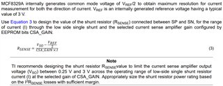
    For example, using the equation above, let's say if you expect your peak phase current will be 5A, and we choose to use CSA_GAIN = 5V/V, plugging in VSO = 3V, VREF = 3V, I = 6A,

    3 - (3/2) / (5 * 6) = 0.05 Ohm = 50mOhm

    Regards,
    Eric C.

  • Hi Marc,

    Correction to above statement about different CSA_GAIN settings performance, a major consideration would be to appropriately size the shunt resistor power rating based on the I2RSENSE power losses to ensure there is sufficient margin. A higher RSENSE can result in higher power losses, while lower RSENSE resistance can be more susceptible to noise.

    Regards,
    Eric C.

  • The key question for selecting the CSA_GAIN setting is what the CSA input noise and offset are relative to the ADC resolution.  If those values times 40 are less than or comparable to the ADC resolution/noise/accuracy, then using a gain of 40 V/V allows the power in the sense resistor to be minimized.  If however the CSA would contribute to inaccuracy at that gain level, then it is better to use a lower gain and higher sense resistor value, dissipation allowing.  Only TI can provide that information about the CSA input noise and offset, as well as the practical resolution of the ADC.  Please ask the development team what the situation is.  I'd like to size the sense resistor based on the actual engineering data, rather than guessing!

    The other piece that would be helpful would be a rule of thumb as to by what factor the instantaneous bus current can exceed the average bus current, worst case.  This will allow optimal scaling of the sense current range.

  • Hi Marc,

    The ADC full scale voltage is 3.3V and with 12-bit resolution, each ADC count corresponds to ~0.8 mV.
    And based on our internal characterization data, the CSA input offset voltage after multiplying by 40V/V gain is still much lower than 0.8 mV by about a factor of 10.

    The amplitude of your instantaneous bus current can depend on your VM bulk capacitance and your device configurations. Settings such as how fast you will accelerate/decelerate your motor, whether AVS (anti voltage surge) type protection settings are enabled, etc.

    Regards,
    Eric C.

  • That's pretty good.  If the CSA really has 2 uV Vos, it must use a chopper architecture or some other correction method.

    My concern about the bus current is to scale the sense resistor and CSA gain to prevent clipping.  It would be great if the chip incorporated some current sense overrange fault detection.  Is there any way to look for that situation?

  • Hi Marc,

    The device does not have a way to notify or fault in the event of CSA output clipping. The best way is to directly monitor the CSA output on the SOx pin for any clipping.

    Regards,
    Eric C.