This thread has been locked.

If you have a related question, please click the "Ask a related question" button in the top right corner. The newly created question will be automatically linked to this question.

DRV11873: How to calculate the output power of a driver

Part Number: DRV11873

Hi team,

  For the title says, I have a motor with a rated power of 20 W. How do I calculate the output power of the driver to ensure that it can drive the motor?

  For example, how to calculate the output power of the driver at a set voltage? Can you tell me the calculation method?

  • Hi Suy, 

    Thanks for your post to the e2e motor drivers forum.

    Many of our team members are currently out of office for US holiday timeframe - but will be back in office by 1st week of January.

    Please anticipate a delayed response & feel free to provide additional information in the meantime.
    Best Regards,
    Andrew

  • Hi Suy,

    What is the rated voltage or current of the motor?

    Let me take example, let us consider 12V as applied voltage then you motor may be driven close to 1.5A.

    DRV11873 can be configured for current limit through a resister (R cs) - If we use 6.8K resistor on CS pin it can deliver up to 0.97A

    Also read the highlighted line in the data sheet, during startup to provide good starting torque device will deliver 1.5 times to current value set by Rcs. In this case it will be approximately 1.5A. This will make sure motor should startup and then goes to closed loop by reducing current to 0.97A.

    When motor is spinning back EMF builds up and current through the Widing reduces.

    The effective power will be Power  = Speed *  Torque

    Assume a Ideal system,  Pin (Input Power)  =  Pout (Output power)

    Pin =  Vdc * Idc

    Pout =  Speed *  Torque =  Ea*ia + Eb*ib + Ec * ic. Where Ea,b,c are BEMF and ia,b,c are phase current in phase to BEMF

    Please let me know if this is clear.

    Thanks and Best Regards,

    Venkatadri S

  • Hi Venkatadri ,

      Much appreciated for your reply.

      As you said above, i have some questions:

      1,In the formula of “ Pin =  Vdc * Idc ”,the Vdc is the VCC of the DRV11873,and the Idc is the overcurrent?

      2,Assume a Ideal system,  the Pin=Pout,But is it necessary to multiply the efficiency of a motor in practical applications? 

      3,In the formula of “ Pout =   Speed *  Torque = Ea*ia + Eb*ib + Ec * ic ”,i found the speed,Torque and BEMF in the specification,Are the BEMF and current mentioned in the motor specification three-phase BEMF and phase current?

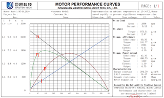
      In the figure below, n represents speed, η represents efficiency, P represents motor power, and I represents phase current,the horizontal coordinate is torque。


      It can be seen from the curve that when the Speed is 600rpm (8V motor drive power supply, duty cycle is 30%), the corresponding motor power is 4.8W according to the Pout = Speed * Torque formula, but the input power is only 1W, and the motor is driven at work, the input power is smaller than the motor power. This makes me very confused, may I ask how the power of the motor should be calculated in this case?

  • Hi Suy,

      1,In the formula of “ Pin =  Vdc * Idc ”,the Vdc is the VCC of the DRV11873,and the Idc is the overcurrent? 

    This is bus current (DC Bus)

      2,Assume a Ideal system,  the Pin=Pout,But is it necessary to multiply the efficiency of a motor in practical applications? 

    Yes you are correct. Motor losses needs to accounted- losses are windage friction, viscous, winding factor etc I just provided generic Power balance method.

      3,In the formula of “ Pout =   Speed *  Torque = Ea*ia + Eb*ib + Ec * ic ”,i found the speed, Torque and BEMF in the specification, Are the BEMF and current mentioned in the motor specification three-phase BEMF and phase current?

    Data sheet provided BEMF constant at a reference speed, we have to multiply this with motor speed to get BEMF built on the phase.

    Example:  From the data sheet EMF Constant is 35.363mV/rad/sec. At say 2000 rpm (209 rad/s) the BEMF developed will be 35.363 * 209 

  • Hi Venkatadri,

       I am very sorry that I did not see your reply in time, so I edited my reply again just now.

       Please take a look at the last question in the previous post, which is mainly the problem of motor power that I can't understand.

       When the speed is 600rpm, the motor power P=600*780/98000≈4.8W.

  • Hi Suy,

    I am out if office until Jan 2nd.  I will go through the motor spec and verify it.  

    We need to verify Torque (kt * Current) at 600 rpm , whether it is no load or load please verify. 

    Thanks and Best Regards, 

    Venkatadri S

  • Hi Venkatadri,

       OK,i look forward to your verification.   

    Another information I just got from the motor manufacturer is that this curve is obtained by continuously increasing the load when the PWM duty cycle is 100%, and  we actually use a relatively light load, and then control the PWM duty cycle to control the speed. I don't know whether the torque of the motor under the same speed is linear in these two cases.
    Thanks!

  • Hi Suy,

    thanks for the additional information - 

    Many of our team members are currently out of office for US holiday timeframe - but will be back in office by 1st week of January.

    Please anticipate a delayed response & feel free to provide additional information in the meantime.
    Best Regards,
    Andrew

  • Hi Suy,

    What type of load is this? Fan or Pump?

    Can you please provide me the reference for scaling used (780/98000 scaling).  I am sorry if I am missing some information.

    Thanks and Best Regards,

    Venkatadri S

  • Hi Venkatadri,

      I am very sorry for accidentally closing this issue.

      The load of the motor is the lens group, which weighs about 100g.Our requirement is that the motor speed is 600rpm, but there are two problems at present: First, there is a situation of stalling in the working process of the motor, and the measurement of UVW three-phase signal is found to be lost. Second, the motor will stop working and restart after 1s. The adjustment duty cycle and voltage in both cases still exist, and it is not known whether it is related to the motor.

  • Hi Suy,

    Lock detection and release time is as per the table shown below. 

    Did you try increasing the current limit to higher? Can you try lower RCS and increased ILIMIT should help to maintain the torque.

    Thanks and Best Regards,

    Venkatadri S

  • Hi Venkatadri,

    I've tried setting ILIMIT to maximum, but it still comes up. Do not know whether the drive power is insufficient?

    As you said above the driver output power calculation formula “P=Vdc*Idc”, the maximum output power is equal to Vdc Multiply by starting current of the motor ?

  • Hi Suy,

    Can you please share the CRO capture of a phase current?

    Yes, max output power drawn from the supply is starting current which is 1.5 times the ILIMIT.

    But where it is failing, we need to understand. 600 rpm seems to be lower, what is the max speed? Did you check if this runs reliably at higher speed range?

    Thanks and Best Regards,

    Venkatadri S

  • Hi Venkatadri,

    There was no problem with the drive, and finally it was found that the spring on the motor bearing caused the phenomenon of stalling and stalling, and it was normal after re-processing.
    Thank you very much!

  • Hi Suy,

    Thanks for confirming. 

    If you are not seeing anymore issue please help to close this by clicking Resolved and we can start on new thread for fresh discussion.

    Thanks and Best Regards,

    Venkatadri S