This thread has been locked.

If you have a related question, please click the "Ask a related question" button in the top right corner. The newly created question will be automatically linked to this question.

DRV8718-Q1: unused SHx pin

Part Number: DRV8718-Q1

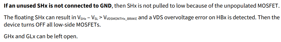
What to do with unused half-bridge SHx? Floating or grounded?
If the mos of the unused channel of DRV871x is not attached and SHx is floating, how to ensure that when overvoltage brake occurs, LS4~LS8 will not fail the overvoltage brake function due to VDSOV false alarm? Because SHx in the datasheet is not grounded internally.

  • Hi Mingkang,

    The general advice we provide to customers is to leave the unused half-bridge GHx, GLx and SHx not connected (floating). This is assuming that this unused bridge driver will not be commanded to turn on. Because if it was turned on it will report errors. Firmware must never command this unused HB to turn on.

    If the customer will be using POB (powered off braking), and the unused half-bridge is in the set of 4 POB enabled half-bridges 5, 6, 7 and 8 (DRV8718-Q1). Then when the POB is enabled the unused half-bridge LS driver will also be activated and due to the floating SHx and activating the LS VDS, could cause false fault like mentioned. So we would need to address this use case. The POB function is not available on half-bridges 1, 2, 3, and 4 on the DRV8718-Q1 device. It would be a good idea to have the unpopulated MOSFETs with HB 1, 2, 3 and 4 so we don't need to be concerned about POB causing a VDS error. Can you please check with the customer if this will be an implementation solution for them. Thanks.

    Regards, Murugavel

  • Hi Mingkang,

    I also checked with our team and confirmed it is okay to connect the unused SHx to GND. There would be a very small leakage current from SHx to GND while in active mode ~ 100 uA which will not impact the performance of the device. I hope this will help you close with the customer. Thanks.

    Regards, Murugavel

  • Hi Murugavel

    When customer not populate MOSFET at HB7 and HB8, does it require connect SH7 and SH8 to ground? Customer is connecting the SH7 and SH8 to ground through 10k resistor, is it okay?

    Thank you

    Scarlett

  • Hi Scarlett,

    SH7 and SH8 must be directly to GND or use 0 ohms. With 10k because of the leakage current there will be ~ 1V on the node.

    Regards, Murugavel 

  • Hi Murugavel,

    In the application, when the channel is not in use, the SHx is wired to the port PIN even if devices such as MOS are not attached, and if directly grounded or 0Ω grounded, there may be wire burning or resistance damage when the SHx SCB occurs. As you could see below, 0402 resistance is 1/16W, after high temperature derating is 30mW, 16*16/R needs to be less than 30mW, so R>8.5k.  The customer think the VDSOV false positive of the channel that is not used can be shielded by the software. Is it true? Please confirm the resistance value selection when the channel is not used.

    Thanks for your help.

    Mingkang

  • Hi Mingkang,

    My assumption is the port pins are configured as inputs not outputs. Is this correct? So if they are inputs there should not be any voltage output from the port.  Anyways if the customer wants to use a resistor they should be aware, because of leakage current possible up to 150 uA from the SHx will result with some voltage = I(leakage) * R on the pin. So assuming 10k will be used the voltage on it could be up to 1.5 V.

    "The customer think the VDSOV false positive of the channel that is not used can be shielded by the software. Is it true?". Yes they can do this.


    Regards, Murugavel

  • Hi Murugavel,

    The port PIN needs to consider the possible short to Vbat condition, which is independent of the configuration as input or output

  • Hi Mingkang,

    Thanks for the clarification. I hope the info in my previous message helps in determining the resistor value. That said, I also want to point out if the customer is using these resistors to detect a open load we already have that feature integrated in the device and we recommend using it instead of an external circuit. May I know the purpose of these resistor divider based inputs to GPIO? Are they digital status or analog input of the MCU? Why it is done for unused output only? 

    If these resistors are for all channels can get a schematic and purpose of these GPIO connections? 


    Regards, Murugavel