This thread has been locked.

If you have a related question, please click the "Ask a related question" button in the top right corner. The newly created question will be automatically linked to this question.

DRV8306EVM: Fault help please

Part Number: DRV8306EVM
Other Parts Discussed in Thread: CSD88584Q5DC, DRV8306,

Hi,

My company makes a range of products which use BLDC motors. The control board for this range uses a DRV8306 coupled with 3 x CSD88584Q5DC to drive each motor, with each board driving a total of 2 motors (side A & B). This drive circuit is essentially the same as the DRV8306EVM evaluation board, so for this question please use that as a design reference.
After much work/testing/compliance (and help from this forum!) - this product range was released to the market 2 years ago. Since then we have sold hundreds of units around the world, and they have proven extremely reliable - with no faults directly related to the drive circuitry. Nice :) 
However recently we received 4 x control boards back from a new customer. These units worked for several weeks, then would no longer drive the motors. We had only supplied them with 8 units total, so this was very strange indeed. 
On checking the boards I found 3 which show the same issue on both sides A and B. 
After start-up, our system is normally in brake mode - so GHx are all OFF, and GLx are all ON (10V wrt SHx). 
On these units though, at startup GLx is 0V and GHx is showing 24V wrt GND (note: VM = 24V in our system). 24V is also seen on all outputs / SHx i.e. there is no differential between GHx and SHx. This state does not change either when you attempt to activate the motors. Again, this is the same on 3 boards, both sides A and B - so 6 x drive circuits in total.
On the 4th unit, one side is still working. On the other side though, it will power up into brake mode as normal (GHx are all OFF, and GLx are all ON). However, if you try to activate the motor, it will not start and the circuit will then go into the state mentioned above - GLx = 0V and GHx/SHx = 24V / VM
I just saw the interesting FAQ by  re: Why do SHx and GHx Float? This seems to explain what I am seeing i.e. GHx is essentially shorted to SHx. If so that would mean both the low-side and high-side FETs are not on - however that should not be the case!
So onto my questions - does the above sound likely (both high and low FETs are off) and if so - does that mean these FETs have failed in some way? and if so, what are the most likely causes of this type of failure?
OR could it be an issue with the DRV8306 failing to turn the FETs on? I have checked the key inputs to the DRV (nBRAKE etc) and all seemed normal there. The last thing to note is this circuit is over-specified for our application - our motors are 24VDC and run below 3A (and less than 1A in the product(s) which saw these failures) - so considerably under the ratings for the CSD88584Q5DC.
Any input would be great appreciated and please let me know if I can provide more data to assist. Thank you!
  • Hi Adam,

    Can you check the voltage of the VCP pin, it should be roughly equal to VM+10V?

    Does the fourth unit's nFAULT pin get pulled low when attempting to drive the motor?

    Regards,

    Joshua

  • Hi Joshua,

    Thanks for the response!

    VCP is VM+10V (34V) - I checked on two of the faulty units so far, both were the same.

    nFAULT pin does not get pulled low when attempting to drive motor on fourth unit.

    Any ideas?

  • Hello Adam,

    Have you preformed an ABA swap of the DRV8306 to see if the issue follows the DRV8306 or the board?

    Can you also provide a capture of GHx, GLx, SHx, and the input PWM for both of the DRV8306s on the fourth unit when going from brake mode into spinning the motor? 

    Regards,

    Joshua

  • Hi Joshua,

    No I haven't tried an ABA swap, I don't have experience soldering SMT - but seems it might be time to learn. 

    I'll get the requested captures and get back to you, this will likely be early next week. 

    Thanks again and let me know if you have any other thoughts.

    Adam

  • Hi Joshua,

    I tried to get the captures you requested, but that unit behaved differently when I retested - going into the fault mode straight after turning on, instead of Brake mode. So I couldn't capture any change, I did check the PWM again and it was ok. I have captures of a 'good' side for reference, but if you read on I don't think these will help.
    After more investigating I found the following. Just to note again, each board has two motor driver circuits or Side A & B - so I refer to each of these driver circuits as 'sides' 
    Of the 4 boards, there are two main fault conditions which each side falls into.
    FAULT CONDITION 1  
    These sides will show the same fault (GHX=24V, GLX=0V) during idle and when trying to spin the motor. Also this fault is the same with or without a motor connected. The fault presents ars GHX=24V, GLX=0V at all times.
    FAULT CONDITION 2 
    These sides will startup into Brake mode, then the fault presents as follows:
    • By manually rotating a connected motor, you can position it where the motor will start again. The motor will then run several times, before landing on a 'bad' spot - then the fault would re-occur. To be clear, this was a normal motor with no issues.
    • Once the motor landed on the 'bad' spot, the fault condition looked like this:
      • WITH MOTOR PLUGGED IN: 
        • GHX = 24V, GLX = 0V
      • WITH NO MOTOR, IDLE:
        • GHX = 0V, GLX = 10V (brake mode)
      • WITH NO MOTOR, DOSE ACTIVATED:
        • GHA = 24V
        • GLA = 0V
        • GHB = 0V
        • GLB = 10V
        • GHC = PWM
        • GLC = PWM
    • On 2 of the sides when in the 'bad' spot, the hall effect signals were as below
      • HPA = Low
      • HPB = Low
      • HPC = High
    • On another the two sides, the HPC signal was unable to go High, so on that side the 'bad' spot was the same, but with a Low for HPC (note: the hall sensor in the motor was ok, this is an issue with the board).
    • Manually rotating the motor again (with it plugged in) would then move the hall signals to a different configuration, and the fault would clear instantly / the motor would restart.
    • The above hall signal configuration occurs several times as the motor rotates, in each spot - the fault would occur. It would not occur with the hall sensor in any other configuration.
    After noting the hall signal issue, I then looked more at the hall sensor circuit and found:
    • On the sides that show  FAULT CONDITION 1  - there is no output from the Hall comparator output FGOUT. i.e. Normally if you manually rotate the motor, you can see FGOUT changing from High to Low. On these circuits though, it just stays Low - however the hall effect signals are changing as the motor rotates. 
    • HPA and HPB read 3.2V when high, and normally HPC only reads 2.7V when High on any board (I understand this is due to an issue with the DRV8306, but it should not cause faults as the signal is still high enough). However on some faulty circuits, the HPC voltage was lower again i.e. 2.3V, and in two cases as mentioned - the HPC signal could not go High (stays at 0V)
    • I checked the resistance between HPC and GND on those two cases where the signal can not go high, and it was basically shorted to GND. One was 2.2Ω and the other 47Ω. Then on other faulty boards, it wasn't shorted but the resistance seemed low between HPC and GND (and also between HPA + HPB and GND). For example, I measured 8.5K on some sides and for a good/new board, the resistance is 22.8K between any HPX signal and GND (measured from test points). 
    • The resistance between HNX and GND was lower than normal in some cases too.
    • For the sides which show FAULT CONDITION 2 - FGOUT is still working. However as mentioned, once the hall effects are in a certain configuration - it will go into fault. I haven't quite figured this part out yet, but it seems related to the Hall effect circuit also.

    Does this seems to point to something damaging the hall inputs and/or the comparators on the DRV8306?
  • Hello Adam,

    There does seem to be an issue with the motors hall signals to the DRV8306 either internally or from the board.

    What voltage is being used for the pull-up resistor on the HPx pins, assuming you are using digital hall sensors?

    For both Fault conditions, can you provide a capture of the hall signals as close to the HPx pins of the DRV8306 as possible?

    For the devices experiencing Fault Condition 1, what voltage is being output by DVDD? IF DVDD is not outputting 3.3V can you try supplying the ENABLE pin with 5.5V and check DVDD again?

    Regards,

    Joshua

  • Thanks yet again Joshua.

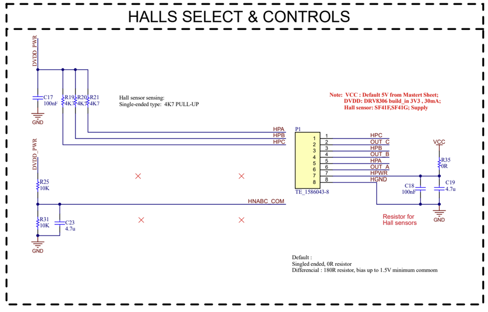
    Below is our hall + DRV8306 circuits. As shown HPx pins are pulled up to DVDD via 4.7K resistors. Also DVDD on all faulty boards was 3.3V when I checked initially. I will double-check this though. I can capture the hall signals close to HPx pins as we have test points right there. 
  • Hi Joshua,

    DVDD was 3.3V on rechecking (or very close to that). Below are some captures of the hall signals + PWM. Sorry for the photos, this is a new scope which arrived today, so didn't have time to learn the capture process :) 

    This side has fault condition 2. I tried to capture the change when it goes into fault, but no success yet. 

    Below is a 'normal' unit

    As shown there are pulses from the PWM signal appearing on the hall signals (when the signals are high). These pulses are higher on some signals compared to others. One difference between the fault unit and a normal unit, is these higher pulses are more consistent throughout the high signal. 

    Please let me know if you have any feedback on this. 

  • Hi Adam,

    Please allow me some time to look into this. I will aim to get back with you by Wednesday of next week.

    Regards,

    Joshua

  • Hi Joshua,

    That is completely fine, thanks for taking the time to look into this further. 

    I just wanted to include the below captures to potentially assist. These are all from a side has fault condition 2.

    1. Hall effect signals at motor stop

    HPA=CH1, HPB=CH2, HPC=CH3, FGOUT=CH4

    These we captured by first going to the bad spot (HPA=0,HPB=0,HPC=1), then moving the motor back to the previous position (HPA=0,HPB=1,HPC=1). So on the next start, the motor moves briefly then stops. As shown, at times it will stop straight on 'bad', and others it moves briefly to the next position, then back to 'bad'. Note: our system has a soft ramp-up to start the motor. If I made this ramp faster or removed it - the motor would then start from the position before the bad spot i.e. it would then only not start if actually on the bad spot. 

    Stop on bad:

    Stop on bad after brief move to next position:


    Spinning (with what looks like a rough start-up)


    2. GHx signals 

    GHA=CH1, GHB=CH2, GHC=CH3, FGOUT=CH4 (all wrt GND)

    As shown GHx signals are not correct - the 'GHx=24V' fault is occurring repeatedly throughout the commutation process. I also noticed the motor pulling higher than normal current. 

    Commutation on fault 2 side:

    Failed start (stopped on bad spot):

    Good unit for reference:

  • Hi Adam,

    In the captures that you provided the hall signal on channel 1 exceeds the absolute maximum value for the HPx and HNx pins which is DVDD (~3.3V). The absolute maximum value violation may have lead to internal damage within the device. 

    I would recommend placing a capacitor, with a value between 1nF to 100nF, between the HPx and HNx traces to try and mitigate the noise being coupled onto the hall signals.

    Regards,

    Joshua

  • Hi Joshua,

    Thanks for your input. I agree the noise is an issue, it is being coupled from the phase to the hall signals in the multicore cable going to the motors. We have started testing with capacitors as suggested and it removed the noise. We need to do more testing though as the 100nF cap we started with added a curve to the hall effect signal as shown below. So we will do more testing with different values and then implement this on the board as an update.

    I'm still puzzled by the fault though. All units I've tested (good and failed) show this noise. However, we have +350 boards in the field, some for several years now - with no faults. We also successfully conducted a +1M cycle life test before launching this product range. Then in this one batch of 8 boards, 4 failed within the first month. This week we started a new life test to be sure, and it is already well past where these units failed. So I think the noise is involved, but something to do with these particular units made them more susceptible. 

    Anyway, I'll close this as resolved for now....and will update later if something of interest comes up. Thanks for all your help Joshua.