This thread has been locked.

If you have a related question, please click the "Ask a related question" button in the top right corner. The newly created question will be automatically linked to this question.

DRV8899-Q1: Leakage on OUTx

Part Number: DRV8899-Q1
Other Parts Discussed in Thread: DRV8873-Q1, DRV8876-Q1, , DRV8245-Q1, DRV8145-Q1

Hi, TI,

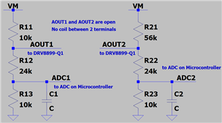
I would like to check with you about the leakage on AOUT1, AOUT2, BOUT1 and BOUT2, when driver outputs are disabled (Hi-Z state)?

and i want to know in which configuration the driver outputs can be set in real Hi-Z state?


During my testing and measurement,

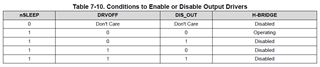
1. if i only set nSleep pin in LOW, i got huge leakage (sink current, max >900uA) on these output pins;

2. if i set nSleep in HIGH and leave DRVOFF FLOATING (internal pull up to DVDD), the leakage became lower, but still in huge values (max >500uA);

3. if i conneted DRVOFF to GND and set bit DIS_OUT=1, no improvement.

This chip is quite different from other ones, like DRV8876-Q1, DRV8873-Q1 .
The leakage on output pins of driver, is too big.

TI, can you please check my setup and share some advices i was wrong during testing. Many thanks!

  • Hi Frank,

    Please clarify, you meant leakage current between OUTx to GND path correct? This leakage is expected and is due to the internal drive circuit for the HS-FETs. The stepper motor coils are connected between AOUT1 and AOUT2 & BOUT1 and BOUT2. There will be no leakage current via the coils when nSLEEP = LOW or when DRVOFF = HIGH. 

    What is the purpose of connecting a load from OUTx to GND path? This is not an intended use for stepper drivers. Thanks.

    Regards, Murugavel

  • Hi, Murugavel,

    Thanks for your comments!

    Here below I clarify the circuits and configuration during my measurement.

    1. In my measurement, between AOUT1 and AOUT2 there is no coil and other connections. In other words, both AOUT1 and AOUT2 are open (this is to emulate the fault condition when motor coil is open);

    2. On each terminal I have a voltage divider (as below) in parallel with the output;

    3. The dividers are supplied by 12-V battery level voltage (in the figure below i use VM, same as DRV8899-Q1 supply);

    4. The on-board microcontroller monitors the divider output for fault diagnostics before enable the motor.

    Then I made 2 measurements.

    Measurement 1: nSleep = 1 and DRVOFF floating externally (internal pull-up to DVDD 5V, so DRVOFF=1).
    VM = 12.9V, V(AOUT1) = 7.9V, V(ADC1) = 2.233V    >>>    so I(R11) = 500uA, I(R12) = 236uA, I(R13) = 223uA    >>>    That means 264uA current sinking into pin AOUT1
    VM = 12.9V, V(AOUT2) = 1.308V, V(ADC1) = 0.386V    >>>    so I(R21) = 207uA, I(R22) = 38.4uA, I(R23) = 38.6uA    >>>    That means almost 170uA current sinking into pin AOUT2

    Measurement 1: nSleep = 0 and DRVOFF floating externally (internal pull-up to DVDD 5V, so DRVOFF=1).
    VM = 12.9V, V(AOUT1) = 2.961V, V(ADC1) = 0.873V    >>>    so I(R11) = 994uA, I(R12) = 87uA, I(R13) = 87.3uA    >>>    That means 907uA current sinking into pin AOUT1
    VM = 12.9V, V(AOUT2) = 1.45V, V(ADC1) = 0.427V    >>>    so I(R21) = 204uA, I(R22) = 42.6uA, I(R23) = 42.7uA    >>>    That means almost 161uA current sinking into pin AOUT2

    The measurement above is for coil open detections.
    Also, we have detections of AOUTx short to battery, short to GND when coil nornal between AOUT1 and AOUT2.
    This is same for BOUT1 and BOUT2, as we are using this chip to drive a stepper motor.

    The leakage (sinking current) is so huge that is not accepted, as it will result wrong diagnostic report. 

  • Hi Frank,

    Thank you for posting additional information. The DRV8899-Q1 has integrated open load OL detection features and integrated over current protection that will detect xOUTx short to GND and short to battery. This stepper driver is widely adopted in the automotive applications. Is your application for automotive? 

    Regards, Murugavel

  • Hi, Murugavel,

    Yes, I agree that DRV8899-Q1 has integrated OL and OC detection feature, which is available during motor running phase.

    My application is for automotive, so diagnostic of fault would be more.

    We want to have fault diagnostic before enable the motor (short to battery, short to GND, open load), so we have the divider in parallel with each output stage. With this divider output voltage (ADCx), and VM level (monitoring by another circuit), microcontroller can know the status of the output terminals. Pity that the huge leakage into xOUTx makes this impossible.
    However, we achieve our target on DRV8876-Q1, which is applied for brushed DC motor driving.
    So i am confused now on your products.

    Then go back to my question:
    1. How to make DRV8899-Q1 output stage in REAL Hi-Z status?
    2. How much of the leakage when it is in REAL Hi-Z status?

    Thank you!

    BR
    Frank

  • Hi Frank,

    Thanks for the clarification that you are trying to detect these while the load is not driven - passive OL and short to VM and GND detection. Some of our brushed motor drivers have these features integrated - both passive and active detection of OL and shorts. Example DRV8245-Q1, DRV8145-Q1. 

    From a load point of view, in Hi-Z bridge disable mode with DRVOFF and nSLEEP, all four NMOS FETs have zero conduction. The leakage is from internal circuit that holds the HS-FET SHx and GHx at a known potential vs. fully floating in bridge Hi-Z mode to avoid spurious conduction of the HS-FETs. Almost all our H-bridges will have some level of leakage paths from VM to SHx depending on the internal circuitry used. 

    For the DRV8899-Q1 there is no way to eliminate this leakage current path. The leakage current from AOUTx to GND or BOUTx to GND is zero while DRVOFF = 1 and nSLEEP = 0 or 1. The leakage current from VM to AOUTx  or VM to BOUTx is approx. 280μA while nSLEEP = 1 (device awake) and DRVOFF = 1 (output drive disabled). The leakage current from VM to AOUTx  or VM to BOUTx is approx. 1.8mA while nSLEEP = 0 (device asleep). Thank you. 

    Regards, Murugavel