This thread has been locked.

If you have a related question, please click the "Ask a related question" button in the top right corner. The newly created question will be automatically linked to this question.

DRV8462: Problem with reading ATQ_TRQ_DAC

Part Number: DRV8462

Hello,
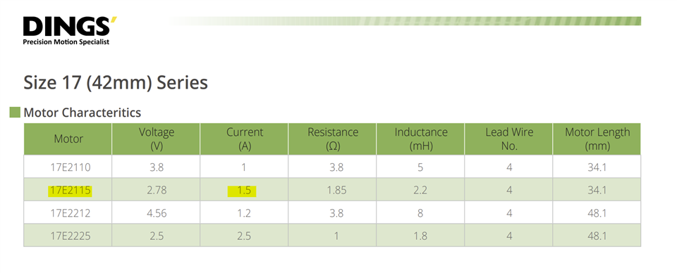
I am using DRV8462 to control stepper motors DINGS 17E2115AB4-69SNSN-130. 

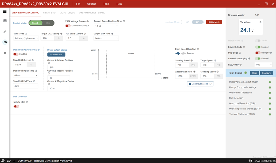
The supply voltage is 24V. I use physical STEP and DIR pins and control other registers via SPI. The motors run with full step and automatic 1/32 microstep with frequency 300Hz. I use stand still power saving, automatic torque and stall detection.

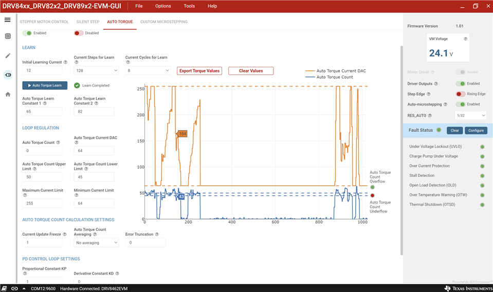
I am trying to read atq_trq_dac register during move of motor, but always value of this register is equal ATQ_TRQ_MAX, despite the fact that ATQ is enabled.

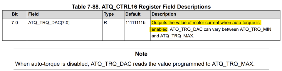
According to DS - "Outputs the value of motor current when auto-torque is enabled. ATQ_TRQ_DAC can vary between ATQ_TRQ_MIN and ATQ_TRQ_MAX."
- When auto-torque is disabled, ATQ_TRQ_DAC reads the value programmed to ATQ_TRQ_MAX.

When I am reading ATQ_EN (ATQ_CTRL10) is set "1" (auto torque is enabled).
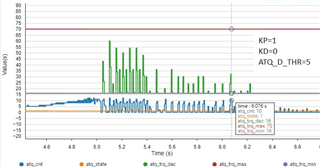
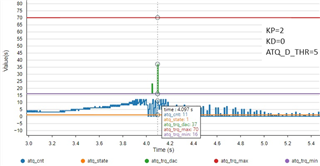
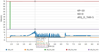
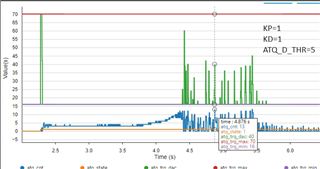
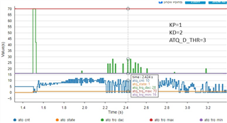
For example atq_trq_min (ATQ_CTRL11) is set 15, atq_trq_max (ATQ_CTRL12) is set 70, and atq_trq_dac read is 70 too, for all move with different weight, when atq_cnt changes according to the moment of load.

I want to use atq_trq_dac to read the current at a given time, when I am using ATQ. Do I misunderstand atq_trq_dac_purpose?

  • Hi Maciej,

    After enabling the auto torque, the tuning procedure for the auto torque must be completed for proper operation of auto torque. The procedure is described in the datasheet as well as this application note https://www.ti.com/lit/an/slvaff1/slvaff1.pdf. Auto toque learn must be completed, KP must be non-zero, typically 1 and Auto Torque Count Upper Limit and Lower Limit correctly defined. After the system is tuned for the setup Auto Torque Current DAC (atq_trq_dac) will read the current depending on the load torque. Thanks.

    Regards, Murugavel

  • Hi Murugavel,

    Thank you for your reply.

    You are right, the problem was Kp=0. But now when I changed Kp to a value other than zero, atq_trq_dac is equal or very close to atq_trq_min.
    I tried with Kp=1 / 10 / 100....
    I tried changing Kd= 5 /10.... and ATQ_D_THR=5 / 10
    I did the learning procedure as in DS, and for 600Hz and automatic microstep 1/32 it gave me these results:
    CONST1=64
    CONST2=125
    ATQ_TRQ_MAX = 70
    ATQ_TRQ_MIN = 16
    ATQ_UL = 31
    ATQ_LL = 29

    When I am turning on ATQ I:

    - Programs the ATQ_LRN_MIN_CURRENT register to a value of 7 - the same as during learning,
    - Programs ATQ_LRN_STEP register to value of 3 - 64 step as during learning,
    - Programs ATQ_LRN_CONST_1 and ATQ_LRN_CONST_2,
    - Sets ATQ_EN to 1,
    - Programs ATQ_TRQ_MIN, ATQ_TRQ_MAX, ATQ_UL, ATQ_LL,
    - Programs KP, KD, ATQ_D_THR

    And later starts engine. 

    The best result is achieved with Kp=1 and Kd=0, but even then atq_trq_dac is far from atq_trq_max. 

    Am I doing everything right? Should it work like this? What should I do to make atq_trq_dac closer to atq_trq_max? Now, the motor stops as soon as the resistance increases.

    Examples of use (an increase in atq_cnt (blue) indicates an increase in load - it usually caused the engine to stop):


  • Hi Maciej,

    I have a similar NEMA17 stepper. I'll try to reproduce this setup. 1/32 Steps, 300Hz seems like a very low speed for stepper that may not generate enough BEMF. Is this the target velocity limit or you could run it higher in your application?

    What is the ATQ_TRQ_MIN and ATQ_TRQ_MAX settings in the ATQ_CTRL11 and 12? What was the VREF voltage input and TRQ_DAC CTRL11 settings used for the test? 

    Regards, Murugavel

  • Thank you for your willingness to help.

    As I mentioned before on these screenshots motor go with 600Hz on full step, I used it as example because on this speed PD works the best.
    In my application, motors must go with velocity from 100Hz to 1000Hz on full step. And I am using automatic microstepping 1/32.
    CONST1=64
    CONST2=125
    ATQ_TRQ_MAX = 70
    ATQ_TRQ_MIN = 16
    ATQ_UL = 31
    ATQ_LL = 29

    Reference voltage source (VREF_INT_EN - CTRL13) I have set to 1 - internal source.

    TRQ_DAC CTRL11 I have set as 70, but it is important when ATQ is enabled?

  • Hi Maciej,

    Thanks for the clarification. The TRQ_DAC, CTRL11 register setting is important when ATQ is not enabled to ensure with the internal 3.3V reference the stepper is not overdriven with higher current when ATQ is not enabled.

    When ATQ is enabled the ATQ_TRQ_DAC will define the motor current, TRQ_DAC settings will be ignored. It is important to set the ATQ_TRQ_MAX to a safe value to avoid burning the motor.

    TRQ_DAC setting will also not affect the HOLD current when ISTSL is enabled.

    Regards, Murugavel

  • Thanks for the clarification. The TRQ_DAC, CTRL11 register setting is important when ATQ is not enabled to ensure with the internal 3.3V reference the stepper is not overdriven with higher current when ATQ is not enabled.

    Ok, I understand, but my problem is when ATQ is enabled. I have set ATQ_TRQ_MAX and the ATQ PD loop has a problem reaching this value (with many different KP, KD, ATQ_D_THR), despite the fact of increasing load and the atq_cnt represented by it, as you can see in the pictures in the first post. The engine will stop faster under increasing load than ATQ_TRQ_DAC will reach ATQ_TRQ_MAX. Do you know where the problem is, what I am doing wrong and what I can change to fix it

    When ATQ is enabled the ATQ_TRQ_DAC will define the motor current, TRQ_DAC settings will be ignored. It is important to set the ATQ_TRQ_MAX to a safe value to avoid burning the motor.

    Ok, I've set ATQ_TRQ_MAX to a safe value of 70, which is something around 600mA, but the motor can operate with a current equal to 1A.

  • Hi Maciej,

    Based on the motor specs it looks like 1.5A is the specified current of the 17E2115 stepper. ATQ_TRQ_MAX can be set to 1.5A. This will allow the ATQ_TRA_DAC to get to higher currents faster.

    The ATQ_TRQ_MIN should be high enough such that at this current the motor will be able to run with the lowest load situation of the application with some 10% torque margin. In your settings I noticed ATQ_TRQ_MIN = 16. The MIN current would be about 137mA. Would this current be enough to drive the motor in the application without stalling while the load torque is minimum? I think this current setting should be higher than what it is now like ~400mA especially with the IFS specification 1.5A.

    I am assuming at 24V you are using the current waveform at IFS = ATQ_TRQ_MAC is looking clean sinewave. 

    The ATQ response time is a function of the motor step rate as these calculations are made at every zero crossing of the electrical cycle of the motor current - zero crossing of the sine wave. I suspect the response time may be slower due to the slower stepping rate of the motor in your testing.

    Regards, Murugavel 

  • Thank you for your reply.


    Based on the motor specs it looks like 1.5A is the specified current of the 17E2115 stepper. ATQ_TRQ_MAX can be set to 1.5A. This will allow the ATQ_TRA_DAC to get to higher currents faster.

    According to DS, I loaded the motor with the maximum load (+30 kg), and ATQ_TRQ_MAX = ATQ_TRQ_MIN = 63 was enough to drive the motor without stalling, so I set ATQ_TRQ_MAX = 70. Do you advise me to set a higher value (but lower than the maximum current) and then the PD loop should work better?

    The ATQ_TRQ_MIN should be high enough such that at this current the motor will be able to run with the lowest load situation of the application with some 10% torque margin. In your settings I noticed ATQ_TRQ_MIN = 16. The MIN current would be about 137mA. Would this current be enough to drive the motor in the application without stalling while the load torque is minimum? I think this current setting should be higher than what it is now like ~400mA especially with the IFS specification 1.5A.

    My application has different load possibilities. It can move without load and with +30 kg load. I learned the parameters according to DS, and with no load ATQ_TRQ_MIN = ATQ_TRQ_MAX = 14 was enough to drive the motor without stalling, so I set ATQ_TRQ_MIN = 16. Do you advise setting it to a higher value?


    The ATQ response time is a function of the motor step rate as these calculations are made at every zero crossing of the electrical cycle of the motor current - zero crossing of the sine wave. I suspect the response time may be slower due to the slower stepping rate of the motor in your testing.

    I understand, but 600 Hz is quite a high frequency. What is the lowest frequency when you advise me to use ATQ? In automatic microstepping mode, I read in DS that it is 10Hz, but about ATQ I did not find such information.
    Now I only have protection against using ATQ with a small number of steps (<20).

  • Hi Maciej,

    "According to DS, I loaded the motor with the maximum load (+30 kg), and ATQ_TRQ_MAX = ATQ_TRQ_MIN = 63 was enough to drive the motor without stalling, so I set ATQ_TRQ_MAX = 70. Do you advise me to set a higher value (but lower than the maximum current) and then the PD loop should work better?". I thought this would give the controller a better range.

    "My application has different load possibilities. It can move without load and with +30 kg load. I learned the parameters according to DS, and with no load ATQ_TRQ_MIN = ATQ_TRQ_MAX = 14 was enough to drive the motor without stalling, so I set ATQ_TRQ_MIN = 16. Do you advise setting it to a higher value?". I had this suggestion because you mentioned the stepper was stalling when it was loaded.

    "I understand, but 600 Hz is quite a high frequency". I missed that part. That you were using full-step and auto microstepping 1/32. For some reason I was thinking 600 Hz with 1/32. I stand corrected. 

    I was analyzing the auto torque operating range and found the operating latitude would be much wider by setting VREF voltage to the desired peak value. This would translate to ATQ_CNT = 255 for the maximum current. Then we can identify the min current by the min torque requirements. In this example lets say we pick 64. This would translate to 376mA (close to the 314mA you set). This would maximize the 8-bit ATQ_CNT operating range and keep it at the upper end where the SNR would be better. 

    With these settings I has no issues with tuning the Auto torque functionality. Please see below screen captures. Thanks.

    You can notice when I manually increase and decrease the load on the motor shaft the ATQ_CNT and ATQ_TRQ_DAC varies as expected.

    Unloaded motor current:

    Loaded motor current:

    Regards, Murugavel

  • Murugavel,
    Thanks for your research,

    I was analyzing the auto torque operating range and found the operating latitude would be much wider by setting VREF voltage to the desired peak value.

    I understand that you get this solution by setting VREF_IN_EN=0 and setting the VREF pin below 3.3V (I think 1.5A/5A*3.3V= 1V) and then the maximum current is 1.5A and you can use full scale ATQ_TRQ? Do I understand correctly?


  • Hi Maciej,

    Yes your understanding is correct. Thank you.

    Regards, Murugavel

  • Ok, thank you, unfortunately now I do not have the possibility to use an external Vref, but I will try to change that and when it is possible I will check this solution.

  • Of course it does work with the internal VREF. I've verified this as well. Just that there will be better latitude with external lower VREF. Thanks.