This thread has been locked.

If you have a related question, please click the "Ask a related question" button in the top right corner. The newly created question will be automatically linked to this question.

MCT8315Z: Motor Driver Selection for Low-Speed PMSM Control

Part Number: MCT8315Z
Other Parts Discussed in Thread: DRV10970, , MCF8316A

Hello,

We are developing a product for an application that requires high control performance with low power. We aim to drive a PMSM (Permanent Magnet Synchronous Motor) in the speed range of -5000 to +5000 RPM using a speed controller while maintaining minimal jitter (less than 1 RPM). Precise speed control at low RPMs (e.g., 5 or 10 RPM) is crucial for our application.

Initially, we evaluated the DRV10970 motor driver, which offers sensored sinusoidal or trapezoidal control for 3-phase BLDC (Brushless DC) motors. The DRV10970 seemed ideal for our low-power application due to its lack of dependency on a C2000 microprocessor and its code-free operation. However, we later discovered that the DRV10970 restricts speeds below 10% PWM command (as indicated in the datasheet). Consequently, we cannot drive the motor below approximately 500 RPM using this driver.

As an alternative, we are considering the MCT8315Z motor driver. However, we are uncertain whether it will encounter issues at low speeds and whether it is compatible with our hall sensor placement. Additionally, while we prefer sinusoidal current for the PMSM, we can accept trapezoidal commutation if it allows operation at low RPMs. Could you please provide an evaluation of the MCT8315Z? Does it have a similar low-speed limitation like the DRV10970?

We also understand that sensorless motor drivers (such as the MCF8316A with field-oriented control) are not ideal for low RPMs due to their technology limitations.

Could you recommend an optimal motor driver and algorithm architecture? Ideally, we need a motor driver that accepts torque commands, performs its own current loop control, and operates reliably at low RPMs. We plan to implement the closed-loop speed controller on a separate board, where we can provide PWM or digital input commands. Additionally, we can incorporate an incremental encoder alongside the hall sensor.

Thank you in advance for your assistance.

Motor Specifications:

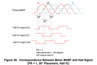
PMSM features: sinusoidal back electromotive force (bemf), 30-degree hall placement, and digital hall sensors, 12V nominal voltage, 7 pole-pairs, 0.66A rated current, phase-phase 6.95 ohm and 884 uH. If needed, we can provide further details.

Best regards,

Gokhan

  • Hi Gokhan,

    The MCT8315Z shouldn't have minimum duty limitations like the DRV10970. However, one thing to watch out for is that that phase current could potentially drop to 0 at lower speeds for motors that have lower inductance, and will cause the motor to stall.

    Within our sensored integrated control drivers, MCT8315Z would be the best fit for your voltage/power requirements. Regarding the device accepting torque command, you could implement a potentiometer to regulate the voltage on the ILIM pin from (AVDD/2) to (AVDD/ 2-0.32) V while keeping input PWM at 100% duty.

    As you mentioned, sensorless motor drivers are limited at low speed operations due to insufficient BEMF. But one way to mitigate that could be with the use of a gear-box so that the driver can still operate above the minimum speed required for sufficient BEMF detection while the output shaft runs at the desired RPM.

    Regards,
    Eric C.

  • Hi Eric,

    Thank you for your email. I appreciate the detailed information you provided regarding the MCT8315Z motor controller. It’s good to know that it doesn’t have the same minimum duty limitations as the DRV10970.

    In DRV10970 datasheet Section 9.1.1, It is explained that motor manufacturers have two popular Hall placement options. The first is 0° Hall placement (BEMF and Hall signals are in-phase) and the second is 30° Hall placement (BEMF leads Hall signal by 30°). We performed the suggested test and discovered that our motor has 30° Hall placement (BEMF leads Hall signal by 30°) like the below Figure 28 (with inverted HALL IC polarity though which can be handled by _HP<->_HN pins).

    Before deciding on the MCT8315Z, we want to ensure whether it optimally supports this 30° hall placement. What is your opinion on this matter? Is the lead angle provided by the “ADVANCE” pin in the MCT8315Z related to this, or is it something entirely different concept? How should we determine the optimized “Advance Angle”, what would be a test procedure?

    Thank you once again for your insights.

    Best regards,

    Gokhan

  • Hi Gokhan,

    The MCT8315Z has ADVANCE angle (aka lead angle) configuration that ranges from 0° to 30° to accommodate the hall placement. This may require some trial and error tuning to achieve the optimal advance/lead angle setting.

    Looks like this older E2E thread has a more in-depth discussion on this topic:
    https://e2e.ti.com/support/motor-drivers-group/motor-drivers/f/motor-drivers-forum/1161803/mct8316z-q1-hall-sensor-placement-0-vs-30

    However, one concern that I have is if your application requires spinning the motor in the reverse direction, the 30° lead angle would become 30° lag angle and may have reduced motor efficiency/performance. Unfortunately, I don't think the MCT8315Z supports negative lead angle configuration.

    Hope this helps.

    Regards,
    Eric C.

  • Hello Eric,

    The phrase "30 degree hall placement" in the DRV10970 datasheet was a bit confusing at first, but eventually, we understood the situation. With the DRV10970, the term "30 degree hall placement" refers to a 30-degree phase difference between the motor phases' B-emfs and the signal changes of the digital hall sensors. If there is a 30-degree phase difference between these two signals (bemf and hall output), it means that the motor phases and hall sensors are aligned (they have a 0-degree phase difference and are positioned with 120-degree offsets). Initially, we thought that the phrase "30 degree hall placement" implied a 30-degree offset between the hall sensor and the motor phases. However, it seems that this confusing phrase hasn't been used in the datasheets of subsequent motor drivers. Since in our motor, the motor phases and hall sensors are aligned at 0 degrees, the MCT8315Z appears suitable for our needs. It will be a good solution as we can operate it below a 10% duty cycle.

    Thank you for your support.

    Gökhan