This thread has been locked.

If you have a related question, please click the "Ask a related question" button in the top right corner. The newly created question will be automatically linked to this question.

DRV8251A: Interfacing DRV8251A with constant current TPS922053

Part Number: DRV8251A
Other Parts Discussed in Thread: TPS922053, , LM317L, DRV8251, , LM317, TPS92515

Hello TI support,

We intend to use DRV8251A in electromagnetic flowmeter application where constant coil current (0.25A) is required. We are using constant current sink LED driver TPS922053. Please see attached schematic details where +24V input is connected as LED+ to VM of DRV8251A & LED- which is VOUT of TPS922053 is connected to GND of DRV8251A. +24V is isolated supplies from digital side having Microcontroller. We intend to drive IN1 of DRV8251A through optocoupler which is referenced to LED- (GND of DRV8251A). Pertaining to this application could you please answer below queries,

1. Do you see any reliability/ operational issues in this scheme for LM317L where GND is floating unless coil (load is connected). That means input to LM317L will be 24V & GND will be floating. Once we connect the coil, VOUT will be equal to 11.5V (24V--50X0.25A).

Regards,

jagdish


DRV8251A_TPS922053.pdf

  • Hi Jagdish,

    Have you done this kind grounding before in a previous design?

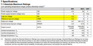
    My concern with having a "floating" ground would be the potential for the input pins to see a negative voltage. 

    If the device exceeds any of the abs max ratings, operation outside the Absolute Maximum Ratings may cause permanent device damage and is not recommended. 

    Best,

    David

  • Hi David,

    No, haven't done this kind of grounding before & hence seek advise from TI. In this application initially GND will be floating but once load is connected GND will be fixed. Field frequency of such instances will be low & this wouldn't be repetitive in nature. There are 3 issues for which we will like to seek your advise. 

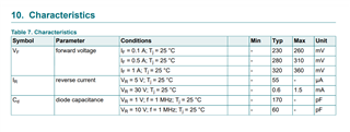
    1. Initially, both GND & 3.3V will be absent so there will be 10K between IN1 & GND of DRV8251. Once load is connected, I think first  DRV8251A GND potential will be fixed & then 3.3V will be generated. If we see possibility of negative voltage, can we have low VF Schottky diode connected between IN1 & GND pins of DRV8251A? Please see attached schematic & specs of Schottky diode as below,

    assets.nexperia.com/.../PMEG3010EP.pdf

    2. Can DRV8251A function properly in such kind of application? Here direction of current in coil will get forward & reverse but direction of current from VM to GND will be fixed.

    3. Can LM317L work in such application where input 24V in present & GND is biased later?

    So want to know long term reliability for 3 points mentioned above. 

    Regards,

    jagdish

    DRV8251A_21032024.pdf

  • Hi Jagdish,

    If we see possibility of negative voltage, can we have low VF Schottky diode connected between IN1 & GND pins of DRV8251A?

    This should work as long as the voltage on the pins remains stable and within the recommended operating range. 

    Can DRV8251A function properly in such kind of application? Here direction of current in coil will get forward & reverse but direction of current from VM to GND will be fixed.

    Yes, the DRV8251A has a full H-Bridge configuration and will allow for both forward and reverse direction. On the schematic it shows IN2 with no connection, however you will be restricted in motor direction by only using one input. See the bridge control table in the datasheet for more details. 

    3. Can LM317L work in such application where input 24V in present & GND is biased later?

    This part is not covered in the motor drivers group, so I will send this post to the appropriate group. 

    So want to know long term reliability for 3 points mentioned above. 

    It is not possible to confirm long term reliability without testing. I would suggest running simulations and bench testing for the design. If you do not already, the DRV8251AEVM would be a great option for bench testing. 

    DRV8251AEVM

    Best,

    David

  • Hi David,

    1. "This should work as long as the voltage on the pins remains stable and within the recommended operating range"

    Once coil is connected, I guess GND of DRV8251A & 3.3V voltages will be stable. Not sure your above statement is meant before connecting coil or after connecting coil?

    2. "On the schematic it shows IN2 with no connection, however you will be restricted in motor direction by only using one input"

    Schematic was just to emphasize connections between TPS922053 & DRV8251A, in fact both IN1 & IN2 will be connected.

    3. "This part is not covered in the motor drivers group, so I will send this post to the appropriate group"

    OK, can I get notification if that query is posted in another group?

    Regards,

    Jagdish

  • Hi Jagdish,

    I would recommend using an LM317 EVM to test this with your other circuitry. I'm worried about other unknown modes of operation that can creep up during the testing phase, in addition to your expected modes of operation while this is in the field.  Just the act of turning on / off bench supplies can result in unexpected scenarios.

    I'm not entirely sure I'm following how this circuit will function.  It looks like the output of the LDO is intended to be the rail for the optocoupler, but a diode routes current around the 10k resistor which would potentially preload the LDO.  You might want a schottky diode across the LDO from Vout to Vin to protect the device in case any reverse voltage exists from OUT to IN of the LDO.

    Is R64 240 ohms? If so, then the output voltage will be 1.25*(1+( 1.5k / 240 ) ) = 9.0625V, not 3.3V.

    Thanks,

    Stephen

  • Hello Stephen,

    OK, we will test this board & possibly have Schottky from VOUT to VIN. Yes, R64 is 240 ohms & that is typo during copy, we will correct that to 901 ohms.

    Regards,

    jagdish

  • Hello David,

    Do you think we can resolve the issue of IN1 & LM317 floating GND by using source constant driver like TPS92515 instead of TPS922053?

    https://www.ti.com/lit/ds/symlink/tps92515.pdf?ts=1711516108516&ref_url=https%253A%252F%252Fwww.ti.com%252Fpower-management%252Fled-drivers%252Fproducts.html

    It looks like GND will remain fixed & stable 3.3V rail will be available. VM to DRV8251A may vary bit but that wouldn't affect other circuit components. Please share your thoughts so we can replace constant current drive scheme.

    Regards,

    jagdish

  • Hi Jagdish,

    From a design perspective the schematic seems ok. 

    As long as the DRV8251A is operated within recommended specifications, it will be fine.

    As I mentioned earlier I would suggest simulating or testing the layout first with the DRV8251AEVM to see if any transient voltages affect the design. 

    Best,

    David

  • Hello David,

    Thanks for your response.We will check and let you know.

    Regards 

    Jagdish