This thread has been locked.

If you have a related question, please click the "Ask a related question" button in the top right corner. The newly created question will be automatically linked to this question.

DRV8701: nFault interrupt

Part Number: DRV8701
Other Parts Discussed in Thread: DRV8706-Q1

Hi,

I am using DRV8701 chip on the following schematics - 

DC Driver #1 Pololu .pdf

At connector A13 I am connecting a DC motor. 

I have issue, when I use the motor, my nFault is going low. I want to fully understand why that happens. 

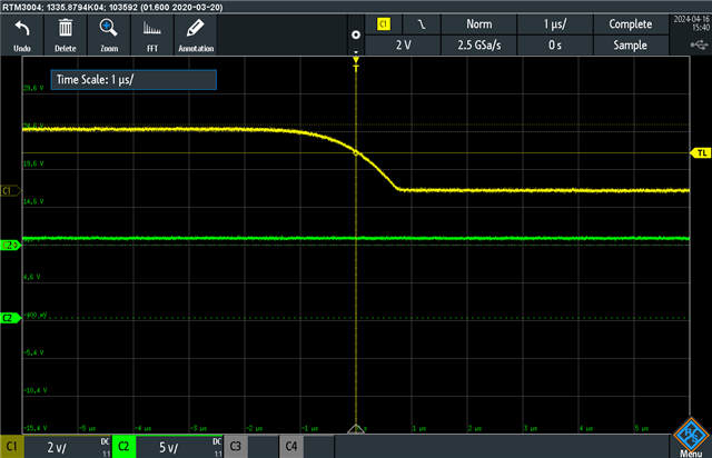
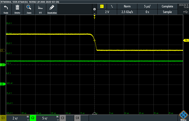
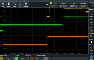
This is the scope of output current and nFault pin - 
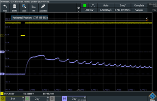
yellow is nFault 

blue is current of the motor 

I can see it happens before the motor is consuming current. I wish to understand why that might happen and how to solve it. 

thank you, 

Michael 

  • Hey Michael,

    Looks like the low pulse is for 1ms, which is interesting since the tRETRY time is 3ms, I would expect at least 3ms long pulse. Can you take a scope capture monitoring VM and VCP as well?  This would let use rule out UVLO and CPUV as the cause.  either of those could reset in quicker than 3ms.  

    The things that can cause nFAULT to go low are listed in 7.3.13 Protection Circuits.  Given that this happens at startup of the motor, I would usually suspect momentary OCP or a Pre-Driver Fault (PDF).  

    Looks like the board has IDRIVE disconnected, which is a setting of 100-mA source and 200-mA sink.  Can you run the calculation for IDRIVE current in 8.2.1.2.2 IDRIVE Configuration and make sure that's the right option for the FETs on the board?  

    Regards,

    Jacob

  • Also if this is a new design you might want to consider one of our newer gate drivers such as DRV8705-Q1.  You'll get a lot more features and better specs for the same price. DRV8706-Q1 would also give you inline current sensing so you could sense current at any phase of the control cycle, vs standard high or low side current sensing. 

    Best,

    Jacob

  • Hi, 

    Thank you for your fast reply. 

    My Qgd is 2.9 nC

    so my current should be - 9.6mA (300nS) to 29mA(100nS) according to section 8.2.1.2.2. 

    I putted a 33k,200K,0 Ohm pulldown resistor at IDRIVE (R236 in my schematics). that didn't fix my issue.

    1. what resistor should be according to my FET's ? 

    2. I would like a further explanation regarding why can't I just put the maximum value as in my initial state. 

    VCP, VM - 

     yellow is nFault.

    green is VCP in top, VM in bottom picture

  • is there any other reason that nFault can interrupt ? 

  • Hey Michael,

    Scope captures look good, VCP and VM look perfectly stable.  

    is there any other reason that nFault can interrupt ? 

    Everything causing nFAULT is listed under 7.3.13 Protection Circuits.  

    Was your device asleep before driving the motor?  Like did you set nSLEEP=1 to start driving the motor? Some of our devices pull nFAULT low during the tWAKE time to indicate the device is not ready to function yet.  

    1. what resistor should be according to my FET's ? 

    Agreed on your calculation, though the rise time is also unique to each fet so 100ns / 300ns might not be the best for your FET.  Given your math I would pick the 12.5 / 25 mA (33 kΩ) IDRIVE setting. 

    See if your FET datasheet has a suggested range of rise/fall times. Understanding MOSFET Data Sheets, Part 5 – Switching Parameters -  https://www.ti.com/document-viewer/lit/html/SSZTCH1 

    2. I would like a further explanation regarding why can't I just put the maximum value as in my initial state. 

    See 2.1 Slew Rate Control For EMC and Power Loss Optimization of that app note.  EMI and switching losses get much worse when using a higher driver current.  

    Best,

    Jacob

  • Hi 

    first I want to say thank you for your fast reply and explanation. 

    I made the test you asked 

    Got new SW with delay of 500mS between nSLEEP set to “1” and start communication with driver

    The problem still exist.


    we have 5 option for Fault Response:


    UVLO – tested, no issues were found, correct ?

    CPUV – tested, no issues were found, correct ?

    OCP –  tested, no issues were found, correct ?

    PDF – TBD, suggest how to test it ?

    TSD – not our case

    I am still not figuring out why I am having nFault issues. I would like your further assistance in that issue. 

    Thank you, 

    Michael 

  • Hey Michael, 

    Give me another day to look into this, I'm not sure.  Does this happen if you use a different load such as a smaller motor or power resistor?  And have you found this behavior with multiple DRV8701 devices and multiple PCBs? 

    You could check for PDF by probing the GHx and GLx pins, see if they try to turn on during tDRIVE but don't get above 1V during that time.  I see it can happen if IDRIVE not sufficient, but we ran your IDRIVE calculations and you tried various IDRIVE settings with far more current than needed.  tRETRY should be 3ms not 1ms anyways.  

    Best,

    Jacob

  • Hey Michael,

    Can you probe the nSLEEP transition and see if the nFAULT pulse lines up with that? 

    According to this thread: https://e2e.ti.com/support/motor-drivers-group/motor-drivers/f/motor-drivers-forum/860380/drv8701-e-nfault-pin-active-1ms-when-turning-bridge-on-or-off, the device pulses nFAULT when entering/exiting sleep mode by design.  

    Best,

    Jacob

  • Hi 

    thanks for replying 

    attaching Scope photo of nSleep, nFault, PWN pin 

    Yellow - nFault, Green - PWM(EN), Brown - nSleep. 

    as you can see, the moment we rise the nSleep, even before generating PWM, we get an instant interrupt in nFault. 

    are there any other pins that may cause this interrupt ? 

    Michael. 

  • Michael, 

    Yes, according to that other E2E thread this is expected behavior, it is part of the design of the device.  When nFAULT goes high after the pulse it indicates the device is awake and ready to function normally.  I recommend just ignoring the nFault signal in your code for x us after turning nSLEEP from low to high. 

    Best,

    Jacob