Hi, TI expert
After the Motor Control Board (featuring DRV11873) produced by the customer is installed in the final equipment, the BLDC motor-equipped water purifier set, intermittent FG detection failure is occurring due to FG output errors.
* Defects occurring during the water purifier inspection process
1) Intermittent FG detection error occurring in the FG output side during the manufacturing process.
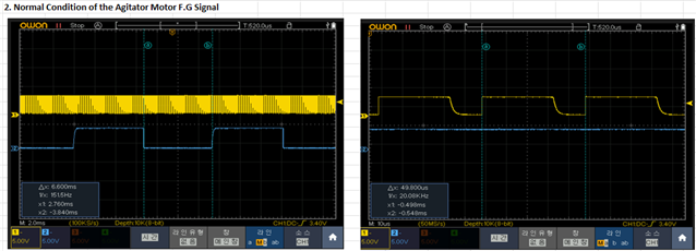
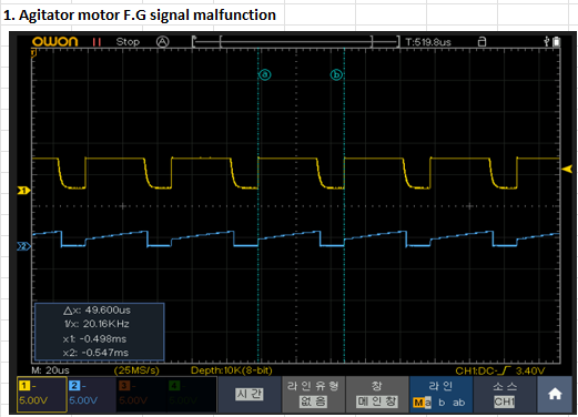
2) The defective product shows a measured FG waveform result of approximately 2.5V level, outputting a PWM waveform frequency (approximately 20kHz) instead of the rotor detection frequency (approximately 151Hz).(See waveform below)
3) When the power connector of the defective product is disconnected and reinserted, normal waveform output is restored upon reoperation. Subsequent tests, upon repeated testing, do not reproduce the same defect.
[Inquiry details]
Q1) 1. After resetting the motor power and restarting, it operates normally. However, since the issue occurs intermittently during the manufacturing process, it is unpredictable when it will occur in the field. Therefore, analysis of the cause and improvement are necessary.
Could you provide advice on the cause and improvement methods?
Q2) There is a 5V pull-up applied in the water purifier circuit and a 12V pull-up applied in the motor circuit. Could this be a potential cause of the error?
Q3) Is it possible to confirm circuitically that there are no issues causing the phenomenon of PWM frequency waveform output on the FG output side when motor errors occur?
Q4) Could you provide any verification methods necessary for identifying the root cause?
Example) Measurement of output waveform due to actions such as disconnection of the FG line after a defect occurs on the FG side, etc.
Please check. Thank you.
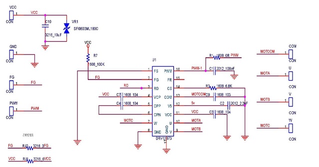
[DRV11873_Board_schematics]
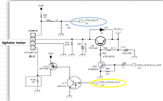
[Agitator motor_schematics]
[1. Agitator motor F.G signal malfunction]
[2. Normal Condition of the Agitator Motor F.G Signal]