This thread has been locked.

If you have a related question, please click the "Ask a related question" button in the top right corner. The newly created question will be automatically linked to this question.

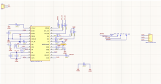
MCF8315C: need to verify the below circuit,

Part Number: MCF8315C

Tool/software:

 please verify the schematic

  • Hello Nirmala,

    Please see my comments about the schematic below:

    1. Unless R9 need to be 5.1k for load balance, we recommend using a 0 ohm for R9.
    2. Do not use a pull down resistor (R9) on nFAULT, use a 5.1k ohm pull up resistor to 1.8-5.0V (AVDD recommended).
    3. Have the buck cap that is connected to pin 6 and PGND connect instead to pin 6 and AGND since GND_BK is connected to AGND.
    4. For R3, R7, R5, R16, and R15 we recommend using a 0 ohm resistor instead of a 5.1k ohm resistor.

    Other than the comments above the schematic looks good!

    Regards,

    Joshua