


Design Resources
- Where can I find the reference design for ULC1001 and DRV2911-Q1
- The ULC1001-DRV2911EVM / ULC1001-DRV290xEVM schematics, layer plots, and BOM can be found in the respective EVM User Guide.
- The ULC1001-DRV2911EVM / ULC1001-DRV290xEVM schematics, layer plots, and BOM can be found in the respective EVM User Guide.
- Where can I find the full datasheet?
- The ULC1001 datasheets are available on Secure Resources in the ULC-DESIGN folder. Access can be granted by request on the ULC1001 product pages. Your request will be reviewed within 1-2 business days.
- The ULC1001 datasheets are available on Secure Resources in the ULC-DESIGN folder. Access can be granted by request on the ULC1001 product pages. Your request will be reviewed within 1-2 business days.
- How do I order the ULC-HPB-DEMO?
- The ULC-HPB-DEMO is orderable through the ULC-HPB-DEMO-DESIGN page in Secure Resources. For access to the ULC-HPB-DEMO, you need permission from HPB Optoelectronics. Please reach out to HPB to ask for permission. Their contact link can be found on https://www.ti.com/partner/HPB. After permission is received, please reach out to ulc@list.ti.com with the approval attached.
- The ULC-HPB-DEMO is orderable through the ULC-HPB-DEMO-DESIGN page in Secure Resources. For access to the ULC-HPB-DEMO, you need permission from HPB Optoelectronics. Please reach out to HPB to ask for permission. Their contact link can be found on https://www.ti.com/partner/HPB. After permission is received, please reach out to ulc@list.ti.com with the approval attached.
- Are there any third parties that develop or sell the mechanical solutions?
- Our ULC mechanical partners can be found at ti.com/ulc. Quick links below.
- https://www.ti.com/partner/EVUSC
- https://www.ti.com/partner/HPB
- https://www.ti.com/partner/MRAAY
- https://www.ti.com/partner/AUWE
- https://www.ti.com/partner/D3
- https://www.ti.com/partner/TDKI3
- Where can I find help videos for ULC operation?
ULC1001 / ULC1001-Q1
- What functionality can be preprogrammed?
- Calibration ranges, cleaning bursts, and sequences can be optimized with our GUI and saved into a header file. This header should then be loaded on power up of ULC1001.
- Calibration ranges, cleaning bursts, and sequences can be optimized with our GUI and saved into a header file. This header should then be loaded on power up of ULC1001.
- Does the device have memory to store it's configuration after power down?
- No, the ULC1001 device only has RAM configurable memory, so it does not store its configuration after power down. A final system can have the ULC1001 configuration or post calibration parameters in the microcontroller. This should be loaded to ULC1001 at every power up.
- No, the ULC1001 device only has RAM configurable memory, so it does not store its configuration after power down. A final system can have the ULC1001 configuration or post calibration parameters in the microcontroller. This should be loaded to ULC1001 at every power up.
- Does a calibration need to be executed at every power up?
- A calibration must be run at least once for every lens cover. A calibration could be run once during the production process and have the resulting configuration loaded to the microcontroller. The configuration then could be loaded to ULC1001 at every power up. Otherwise, a calibration would need to be run at every power up.
- Be cautious when calibrating temperature at power-up due to the external temperature conditions of the LCS.
- What frequency do I use for temperature calibration?
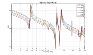
- The frequency chosen for temperature calibration should be far away from any resonant peaks of the LCS. The impedance response at the frequency chosen should also be flat or the change in impedance with temperature will not have a linear slope. Additionally, the point should not have a very high impedance as a low current could be difficult to measure. The impedance response is easiest to view with an impedance analyzer. The below image show various frequency responses at different temperatures and a marking at a spot good for temperature calibration. Similar data will need to be taken for new LCSs to calculate the temperature slope and ultimately set up the temperature calibration correctly.
- Be sure to input the correct Calibration Temperature, USER_Params_tempParams_calTemp_C_Q21, before running temperature calibration. This is the temperature of the LCS environment during calibration.
DRV2911-Q1
- What is the max power output of the DRV2911-Q1?
- Buck: 5.0V to 5.7V, ≤200mA
- Driver: 5V to 35V, ≤8A
- How does the lens cleaning performance change w.r.t. power output?
- In general, more power can lead to better cleaning performance. To increase the power driven, increase the amplitude setting for the burst or the PVDD voltage into the driver.
- When increasing the power to the LCS, the mechanical stress in the lens and glue bond are also increased. Be cautious of increasing the power and causing damage to the LCS.
Lens Design
- How does ULC perform when being used for ice removal?
- ULC can clean ice very well depending on the lens cover system being used. Specifically, the piezo needs to generate enough heat when being driven by ULC to start melting the ice. Very efficient piezos will have a harder time removing ice.
- ULC can clean ice very well depending on the lens cover system being used. Specifically, the piezo needs to generate enough heat when being driven by ULC to start melting the ice. Very efficient piezos will have a harder time removing ice.
- What type of contaminants can ULC clean?
- ULC is very efficient in cleaning water and ice. ULC can also clean some contaminants such as mud and dust. Ultimately what ULC1001 is able to clean is very dependent of the lens cover system (LCS). ULC1001 automatically detects contaminants by sensing a frequency shift. The same water mass will have a larger frequency shift on a light LCS and a smaller frequency shift on a heavier LCS, which could make it harder to detect. The distinguishing factor for a light versus heavy LCS is the lens size, thickness, and density.
- ULC is very efficient in cleaning water and ice. ULC can also clean some contaminants such as mud and dust. Ultimately what ULC1001 is able to clean is very dependent of the lens cover system (LCS). ULC1001 automatically detects contaminants by sensing a frequency shift. The same water mass will have a larger frequency shift on a light LCS and a smaller frequency shift on a heavier LCS, which could make it harder to detect. The distinguishing factor for a light versus heavy LCS is the lens size, thickness, and density.
Total Solution
- What is the power consumption?
- Power consumption is dependent on the load requirements. For TI's flat lens cylindrical piezo prototypes, power consumption can range in the 25-35W range. For TI's flat lens ring piezo prototype, the power consumption can range from 3-5W.
- Power consumption is dependent on the load requirements. For TI's flat lens cylindrical piezo prototypes, power consumption can range in the 25-35W range. For TI's flat lens ring piezo prototype, the power consumption can range from 3-5W.
- What is the cost?
- All electrical IC costs are determined based on volume opportunity. Please reach out to TI for quotes.
- The mechanical cost will be determined by the mechanical suppliers of part, which will not be Texas Instruments.
- What is the max LCS solution size?
- The maximum diameter of a circular lens cover is 40mm per TI's investigations. Larger lenses may be possible, but the cost and complexity will be much higher.
- The maximum diameter of a circular lens cover is 40mm per TI's investigations. Larger lenses may be possible, but the cost and complexity will be much higher.
- What is the smallest PCB solution size?
- ULC1001 + DRV2911-Q1
- 16 mm x 20 mm
- ULC1001 + DRV2901
- 26 mm x 28 mm
- 26 mm x 28 mm
- ULC1001 + DRV2911-Q1
- What is de-icing capability?
- In -20degC environment with ice covering lens: LCS-FL-CYL20
- ~3 min to de-ice with 3W
- ~2 min to de-ice with 5W
- ~1 min to de-ice with 7W
- In -20degC environment with ice covering lens: LCS-FL-CYL20