DRV8462: Stepper motor heating and noise problems.

Part Number: DRV8462

Tool/software:

Hello!

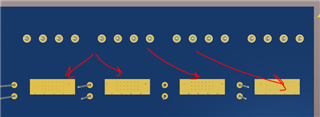
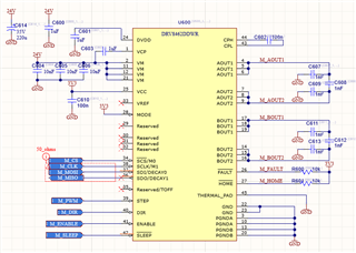
I am developing a board with four 8462DDW drivers whose connections are seen in the image. (In advance, I must say that this is the first time I use stepper motors, so I may not know basic things)
In the Firmware I show you the configuration records of which I am testing:

#define 5 revolutions per seconds
#defin STEP_PER_TURN   200.0

MICROSTEP_MODE = STEP_1_8

TRQ_DAC = 50%

STEP_EDGE = STEP_RISING_EDGE;

VREF_INT_EN = 1;

DECAY = SMART_TUNE_DYNAMIC_DECAY;

The rest of the configuration registers have default values

After 2 hours of testing with the motor running the board starts to get very hot, the motor casing is so hot that I can't even touch it. My question are:
Is it normal for engines to get so hot?
What tips are there to reduce heat within settings?

What opinion do you have about the configuration records that I have given you? Tips for optimizing?

Regarding noise: at 2 hours, the engine emits an annoying noise. It's not strong but annoying if you're around it for a long time.
What elements make it more or less noisy?


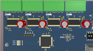
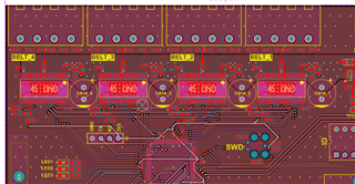
Some data of the PCB:

- The last layer is GND that dissipates heat through a material that is in contact with a metal.

- It is important to point out that the TRQ_DAC register will be at 50% of maximum current. More torque is not necessary, so it makes no sense to go beyond 70% in my application. (70 is the upper limit)

Greetings to all the members of Texas instruments
I hope you can guide me.

  • Hi Antonio,

    Thanks for posting in this forum. You mentioned TRQ_DAC was set at 50% of max. current, so 2.5A. You were using 24V supply for VM. The speed was 5rps. Stepper motors will definitely get very hot with 2.5A IFS (full-scale) when continuously run at 5rps. In your tests how much time the stepper motor was stopped? You can enable the Stand still power saving mode using registers and configuring to a lower current for this mode for hold current, it could be as low as 1% of the max. current. This feature of the DRV8462 will automatically reduce the motor current automatically whenever the STEP pulses are stopped allowing it to cool down between runs. This will also reduce IC heat.

    Looking at the layout, with 4 drivers side by side there is not enough copper to dissipate the hear generated from the driver. How many layers is the PCB and what's the Cu oz of the top layer? You can refer to our EVM layout from the DRV8462EVM webpage https://www.ti.com/tool/DRV8462EVM.

    The last layer is GND that dissipates heat through a material that is in contact with a metal.

    This would be helpful but limited because the heat to conduct via thermal vias and reach the bottom layer will not be as efficient as having thicker top layer Cu and larger area to dissipate.

    In general what you were experiencing is normal behavior both with the motor and the driver at 2.5A motor current. You may want to try the default decay mode Smart tune ripple control. This could reduce heat as well as audible noise. It depends on the motor L and R as well.

    Regards, Murugavel

  • Thank you strongly for replying =)

    After writing in this post i made some little little progress and testing.

    Firstly, I had had my engine running for 2 hours. I was measuring his temperature and it went from 24º to 50º
    I activated the Standstill Power Saving mode (bit EN_STSL = TRUE in reg ctrl12) and and saw no improvement in consumption or savings or reduction in temperature. Could it be that I should have set the TSTSL_DLY and TSTSL_FALL registers? because it kept them with default values. In any case, now I test with new values

    Then I enabled automatic microstepping (the following bits in register ctrl9)

    EN_AUTO = 1;
    RES_AUTO = 1/256;

    This stopped the high-pitched sound produced by the motor coils, which improved the noise. OK ONE THING SOLVED! (for the time being)

    Right now I will study again and try to understand the decay cos I don't really get exactly (:S) i'll try with ripple mode and we will see

    About "You mentioned TRQ_DAC was set at 50% of max. current, so 2.5A".... well, dont' know. I have my tester measuring current on the board and when I turn on 3 motors (1 DRV8462 does not work for me due to a bad connection with the CPU), the tester measures approximately 1.3A with that 50% configuration.
    I imagine that this comment of you means that the maximum current is 2.5A, am I wrong?
    In any case, TRQ_DAC allows me to configure the max torque I need and thus reduce motor consumption a little.

    I want to correct one thing I said "The last layer is GND that dissipates heat through a material that is in contact with a metal". Actually they all have a GND plane and the 4 plates are 1oz each.
    In the last layer I enabled a welding area to insert a thermal material that makes contact with a metal structure.

    The product is ·Thermal Conductive Graphite Sheet" that can be found on mouser. I hope this is useful


    I give stepper I am using: 

    Again, thanks a lot for replying, It helps me both to read and respond, clarifying my ideas as I writting.

  • Hi Antonio,

    I activated the Standstill Power Saving mode (bit EN_STSL = TRUE in reg ctrl12) and and saw no improvement in consumption or savings or reduction in temperature. Could it be that I should have set the TSTSL_DLY and TSTSL_FALL registers? because it kept them with default values.

    Default values for DLY and FALL registers should be fine. but you should also configure the ISTSL value to a lower value compared to its default 0x0 is the lowest. 

    Also standstill power savings will make an impact only when the motor is doing run for some time and stop for some time. For continuous running there will be no impact. 

    For that you can enable auto torque feature in this device where the current will be based on load automatically. It requires tuning. You can read about it in the datasheet and this application note, https://www.ti.com/lit/an/slvaff1/slvaff1.pdf

    Then I enabled automatic microstepping (the following bits in register ctrl9)

    EN_AUTO = 1;
    RES_AUTO = 1/256;

    This stopped the high-pitched sound produced by the motor coils, which improved the noise.

    Yes, this is a good approach. Higher microstepping reduces the motor audible noise.

    I imagine that this comment of you means that the maximum current is 2.5A, am I wrong?

    If you were using 3.3 V for VREF then maximum current would be 2.5 A. It is possible that it does not reach this value if the motor was spinning fast and back EMF is high such that 24 V - BEMF is unable to pump the target current.

    I want to correct one thing I said "The last layer is GND that dissipates heat through a material that is in contact with a metal". Actually they all have a GND plane and the 4 plates are 1oz each.
    In the last layer I enabled a welding area to insert a thermal material that makes contact with a metal structure.

    Thanks. This was what I thought. Still all the heat is immediately dissipated to the top layer. Bottom layer heat is transmitted via the thermal vias so they're less efficient. But definitely will add some improvement. 

    Regards, Murugavel

  • Hello!!! I come with new progress

    First I start with the smart tune ripple mode. This mode is not useful to me because the stepper motor starts making a high-pitched beeping noise. So the decay mode I keep it as is

    The next test was with standstill mode:

    I want to remember that I have set TRQ_DAC = 50%. So I set ISTSL_DLY = 16ms and ISTSL_FALL = 1ms (might be the opposite values, since I'm trying to remember) and ISTSL = 25%

    Really, I didn't see any improvement. I see it working the same as if it were not activated. I don't know what to say here.

    Finally, with respect to heat dissipation, I will necessarily have to do it through the bottom plane, which is the part with which it will indirectly contact a metal structure. How can I improve heat transport from the top layer to the bottom layer? I was looking at the board suggested by Texas Instruments EVM and I have the same thing. The vias are 0.5mm

    In summary, now I am happy with the result I have, but the entire system can always be improved

  • Hi Antonio,

    The best decay mode depends on the motor, target velocity and supply voltage. Looks like you have a good decay mode already STDD.

    Like I mentioned standstill benefit can be realized only if the motor stops with hold current for some period of time. Else you may not see any difference especially if the motor is running most of the time in your tests.

    Understood about your design for heat dissipation. You have followed all the suggested TI recommendations already. We're glad you're happy with the result now. Thank you.

    Regards, Murugavel

  • Yes, I am satisfied.
    Future plans are to investigate autotorque. I find it an interesting functionality to apply.

    I am closing this post because I am finishing this task.

    Once again, thanks for all the help offered ;-)

  • Hi Antonio,

    Thank you very much. Could you please mark this thread status as "RESOLVED" at your end? 

    Regards, Murugavel