Other Parts Discussed in Thread: DRV8718S-Q1EVM
Tool/software:
Hi Team,
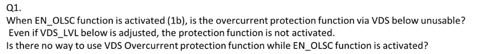
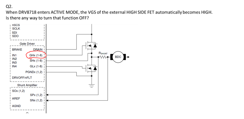
Please check the questions about EN_OLSC function of DRV8718-Q1 and let me know.
Regards,
Tool/software:
Hi Team,
Please check the questions about EN_OLSC function of DRV8718-Q1 and let me know.
Regards,