Tool/software:
Hi,
I have recently received my prototype board for the H-bridge DC motor driver circuit using the DRV8702-Q1.
Schematic can be referred in this thread: DRV8701EVM: Queries on the output current limit - Motor drivers forum - Motor drivers - TI E2E support forums
The design is to current chop 23A during startup, and 40A OCP with the 3mohm Rdson FETs.
However, during my testing I observe some abnormality where the board starts to trip whenever I load more than 20A.
When I further investigate on this, I see that the current spike to 80A and cause the board to trip. But my eload is only set to 20A.
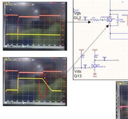
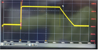
I have scoped all related points for your reference as below:
My test setup are:
2x PLZ334W E-load, 24V Battery, and a MSOS404A mixed signal oscilloscope (differential probe for voltage, current probe for current).
All time is set to 20us, and the yellow graph (10V/div) is voltage respective to each probe point and red graph (20A/div) is the current from the eload (-ve) to the terminal P42 of the board.
For this test only one direction flow from right to left so it is expected only Q10&Q13 is ON.
It is observed that before the current spike, Vgs GL1 (Q14) is suddenly turned to high and Vgs (Q10) GH1 is turned to low. I am unclear why this happen and need your advice how to overcome this issue.
Is this behavior only happening because of using e-load to simulate the motor? Would using a DC motor eliminate this issue? I am still waiting for the DC motor to arrive.
I did also try to connect the eload directly to the battery and no problem found to load more than 20A directly from the battery.
Let me know if you require additional information or any other points to probe, I can provide you the graph.
Appreciate your help on this.
Best Regards,
Amirul


