This thread has been locked.

If you have a related question, please click the "Ask a related question" button in the top right corner. The newly created question will be automatically linked to this question.

DRV8302: MOSFET not turn on

Part Number: DRV8302

Tool/software:

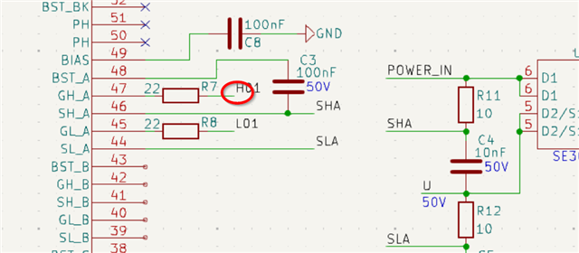
I have designed a 3 phase circuit using drv8302 and mosfet se3082g, below is my schematic connection of 1 mosfet,

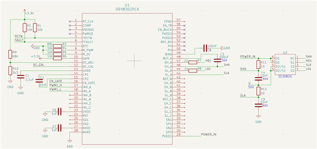
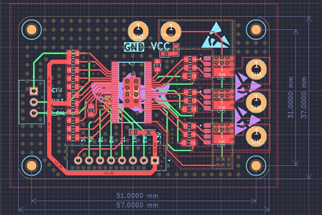
I have printed and soldered 2 boards for testing, supply 12V, provide pwm for INH_A and a complementary pwm for INL_A, non of the boards turn the mosfet on. After messing around (pull the INL_A high first to charge bootstrap capacitor?) and connects/disconnect load, one of board magically be able to turn the mosfet on, and I can control the voltage output using pwm. However I can’t replicate it again on the other board.

  • I have made some tests, and figure out that the mosfet output work fine if there’s load connect between 2 mosfet outputs

  • Hi Nguyen,

    I'm not sure I understand the issue? Have you been able to resolve it?

    Where does this GHA trace lead to? 

    How are you handling your unused phases? There's a guide here on how to do that if you haven't done so already:https://e2e.ti.com/support/motor-drivers-group/motor-drivers/f/motor-drivers-forum/1176539/faq-quick-guide-to-debugging-common-issues-in-bldc-motor-drivers

    Regards,

    Yara

  • Apologize for bad image, here is my full schematic and pcb layout

     Color_Shematic_DRV8302.pdf

    I hook up 12V 10A supply to the board, and use arduino to generate 6PWM to the inputs INH, INL. I expect the 3 outputs SHx will vary between 0 to 12V base on the duty cycle of the PWM, but instead they only output somewhere around 0 to 1.5v. It's like they not fully turn on, Someone told me to switch the low side mosfet on first to charge the bootstrap capacitor?. After messing around, one of the output suddenly work perfect, But I don't know why and can't replicate on another output.

  • Hi Nguyen,

    Are you saying that one phase is working but the others aren't?

    And yes in bootstrap architectures that bootstrap charges while the low side in on.

    While I'm looking at your schematic do you have any waveforms that I can check out? I'd be interested to see you INHx, INLx, GHx to SHx and SHx to GND.

    Regards,

    Yara

  • At first, when I first receive the board and try to test the outputs, give it PWM signals, non of the outputs worked. After many tries without success, phase A worked (and I don’t know why and how). Similarly, I tried to replicate on phase B, it didn’t work at first too, but again when I nearly wanted to give up, phase B worked:). I don’t have a oscilloscope, but there’s one thing, when I turn off all PWM input signals and measure 3 phases with respect to power source GND, phase A and B (which were able work normally) are 12V, phase C (which was not work yet) is 0V.

  • Hello,

    Have you done any testing on phase C?

    What duty cycle are your PWM signals? Are you sure the bootstrap caps are getting charged? 
    the best way for me to understand what is happening in your system is to get waveforms, how are you ensuring the PWM signals you are sending to the device are actually the signals you want without observing it on a scope? 

    Regards,

    Yara

  • My apologies for late reply, my pwm signal freq is 10kHz, duty cycles vary from 5% to 95%. If I keep IN_L high to keep the low side mosfet on, I can measure somewhere around 10V at the bootstrap capacitor, which I think is not enough?. I have a logic analyzer and can confirm the pwm output from the mcu is correct.

  • okay so output SHA on my board is working normally, and the bootstrap A when the low side mosfet on is around 10.5V, bootstrap B and C is only 8V

  • Hello,

    Not sure what issue your experiencing but it seems like conditions have improved from your original post?

    When are you taking these voltage measurements of the phases? Do you have any waveforms to show?

    Regards,

    Yara