Tool/software:
Hi!
I hope you all are doing great!
I am working with a DRV8350HRTVT but facing some problems with proper motor rotation. I am using the following conditions:
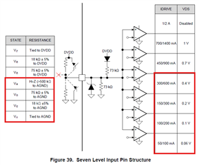
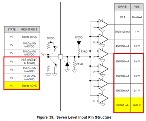
- 1x PWM Mode (MODE Pin, 560k Ohm Resistor, Hi-Z)
- INHC (Dir, LOW)
- INLC (Brake, HIGH)
- Hall Sensor signals are directly connected to INLA, INHB, and INLB without an MCU (proper pull-up resistor and filtering are implemented)
- PWM signal generated by MCU (STM32, 20 kHz, 10% duty cycle only for testing)
- VM/VDRAIN -> Power Supply 16.8V ~ 18V (3A)
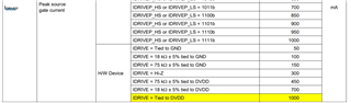
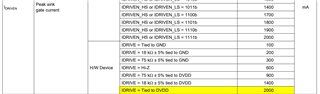
- IDRIVE -> tied to 3.3V
- VDS -> Hi-Z
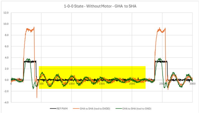
Since the motor was only vibrating I tried to check what was going on with the signals first (hall sensor, phases, GHX, GLX, SHX). I noticed too much noise in some phases and some gates, so before trying to make it work I decided to remove the motor and only check the expected behavior of the driver.
The datasheet provides the following reference:
| DRV8350H (Datasheet) | ||||||||||
| STATE | INHC = 0 | PHASE A | PHASE B | PHASE C | DESCRIPTION | |||||
| INLA | INHB | INLB | GHA | GLA | GHB | GLB | GHC | GLC | ||
| Stop | 0 | 0 | 0 | L | L | L | L | L | L | Stop |
| Align | 1 | 1 | 1 | PWM | !PWM | L | H | L | H | Align |
| 1 | 1 | 1 | 0 | L | L | PWM | !PWM | L | H | B → C |
| 2 | 1 | 0 | 0 | PWM | !PWM | L | L | L | H | A → C |
| 3 | 1 | 0 | 1 | PWM | !PWM | L | H | L | L | A → B |
| 4 | 0 | 0 | 1 | L | L | L | H | PWM | !PWM | C → B |
| 5 | 0 | 1 | 1 | L | H | L | L | PWM | !PWM | C → A |
| 6 | 0 | 1 | 0 | L | H | PWM | !PWM | L | L | B → A |
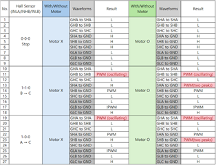
Since I removed the motor I could control the hall sensor signals and check the expected behavior. I obtained the following results:
| DRV8350H (Measurement, No Motor) | ||||||||||
| STATE | INHC = 0 | PHASE A | PHASE B | PHASE C | DESCRIPTION | |||||
| INLA | INHB | INLB | GHA | GLA | GHB | GLB | GHC | GLC | ||
| BRAKE | X | X | X | L | H | L | H | L | H | BRAKE |
| Stop | 0 | 0 | 0 | H | L | H | L | H | L | Stop |
| Align | 1 | 1 | 1 | PWM | !PWM | L | H | L | H | Align |
| 1 | 1 | 1 | 0 | H | L | PWM | !PWM | L | H | B → C |
| 2 | 1 | 0 | 0 | PWM | !PWM | H | L | L | H | A → C |
| 3 | 1 | 0 | 1 | PWM | !PWM | L | H | H | L | A → B |
| 4 | 0 | 0 | 1 | H | L | L | H | PWM | !PWM | C → B |
| 5 | 0 | 1 | 1 | L | H | H | L | PWM | !PWM | C → A |
| 6 | 0 | 1 | 0 | L | H | PWM | !PWM | H | L | B → A |
It seems like the gate for the high-side is not working properly (not for all cases though).
I checked the circuit and driver configuration many times, but I can't pinpoint where the problem might be.
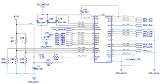
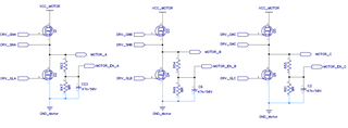
I attached part of the schematic as a reference.
Could you please guide me on what else I can try to solve this problem?
Thanks in advance!