This thread has been locked.

If you have a related question, please click the "Ask a related question" button in the top right corner. The newly created question will be automatically linked to this question.

DRV8412 is dead??? help please...

Other Parts Discussed in Thread: DRV8412

Hello,

I'm working on system for stepper motor driving, and I'm using DRV8412...

I'm working in mode 1 (M1=0, M2=0, M3=0)... PVDD=24V, GVDD=12V, motor is Bipolar 3A, 1,8ohm, 6,8mH...

PWM is 50kHz...

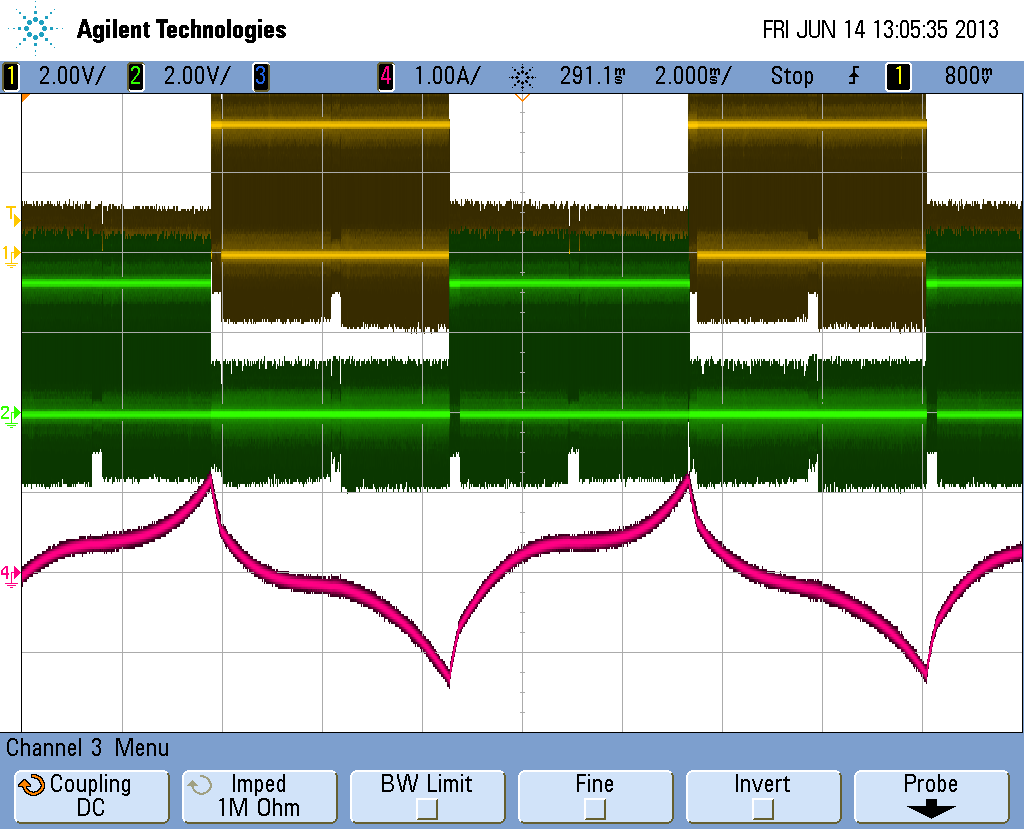
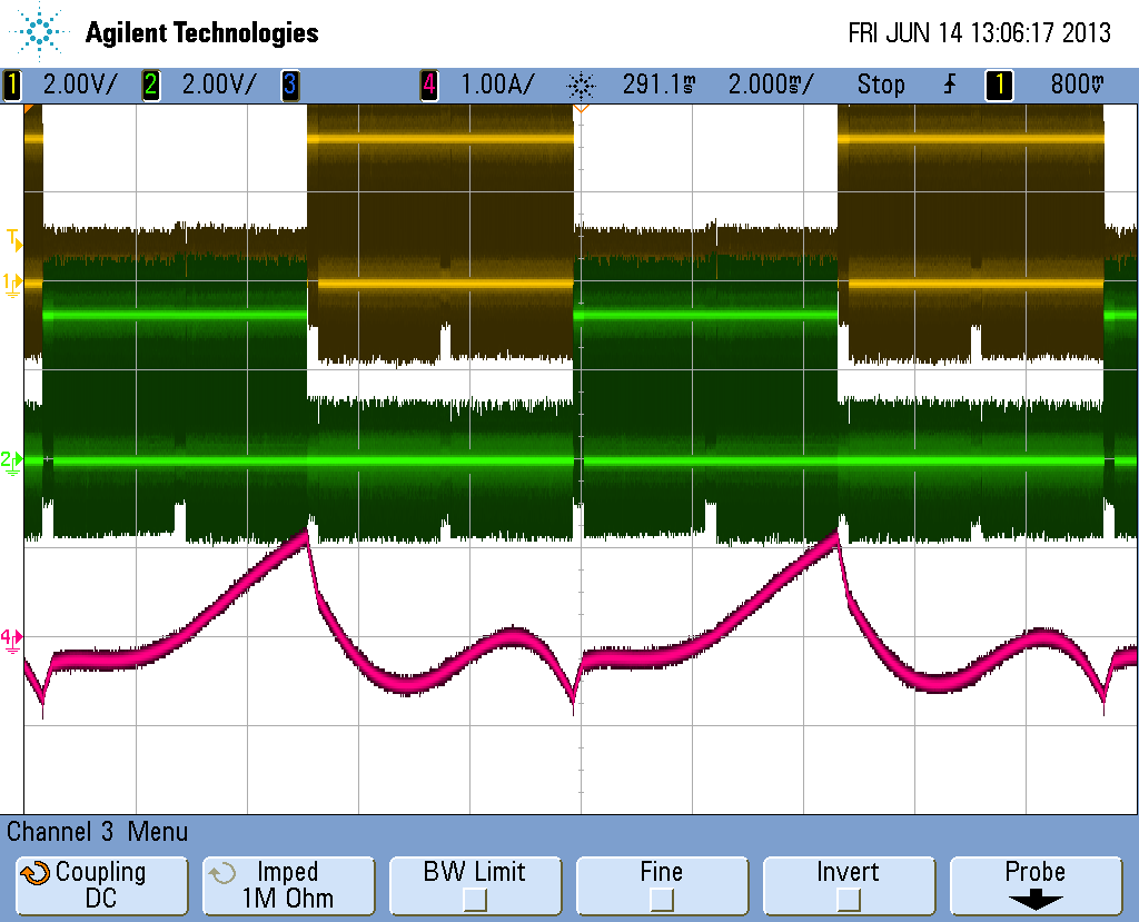
I'm creating four PWM signals which loks like this:

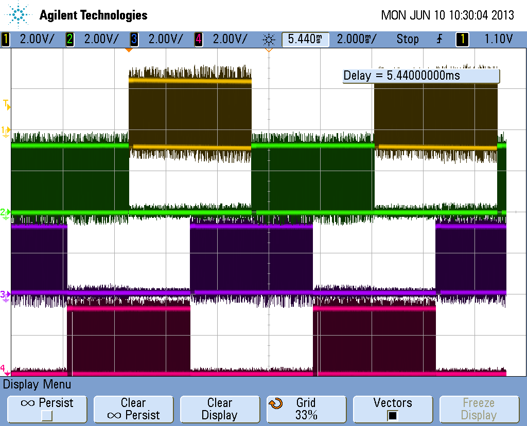
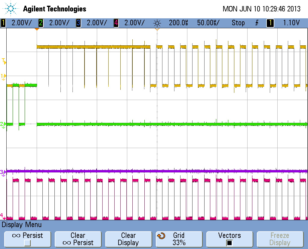
Im trying to move in full step, and I have 100% of PWM duty cycle when i want to grow my current to some value...When I reach that value i'm chopping that current with 50% duty cycle... I'm using Piccolo 28027 to create pwm, and till now i was using PWM chopper module and i get rotation and very big torque... Now when i put this signal from picture my DRV8412 is dead, but i dont know why... When I connected my pwm signals to input at first it was ok and my motor was rotating fine... I tried few times and it was OK in both directions... Then suddenly my drv8412 was dead.... Then i changed PCB where i had another DRV and that drv drop dead too... When i dont have PWM inputs connected my power consumtion from drv8412 is aprox 85mA and when it was working it was aprox 50mA... 

Can you please help me and tell me where I'm wrong and what i have to change to get my driver to work fine????

  • I think that problem was in reconnecting connector on PWM inputs... Can you tell me your experiences with that???

    My driver was working fine and then i was few times reconnect PWM inputs "online" when my driver power and PWM were active to change direction so i think that was mistake because my third driver was in meanwhile dead too... 

    I think that i didnt have too big currents and i didnt overload first DRV and with all protections OTW and overcurrent i think that overloading this driver was not cause of my problem...

    Help please...

  • Ivan,

    Are you using one of our EVM boards or your own board?  Can you share the schematic and layout if it is your own board?

    Power supply decoupling is critical to the operation of this device.  If not properly done, you can get large voltage transients during switching that can destroy the device.  Can you share scope captures of the outputs during switching/load condition?

  • Ryan,

    I'm using my board...

    Here is the schematic and layout

    8666.DRV8412 board_verzija_17_4_2014.pdf

    2110.Gerber_DRV8412.PDF

    When I put power on GVDD and PVDD i get some voltage at output even if on pwm input i have 0 all the time... Voltage on output A and B is 0,6V, and voltage on output C and D is 7V... My current consumption is two time bigger then in normal mode... 

    When I measure VREG to AGND i get some strange values (1,8V or something like that lower than 3.3V...)

  • Now i have changed my DRV8412, but i get same problem... I even didnt put any PWM on input... I doubt that this one is dead too...

  • Ivan, that schematic file appears to be just a BOM.  Maybe you could try re-attaching.

    Does the fact that you changed the DRV8412 device, and see no change in behavior, suggest something else in the system is dead?

    Best regards,
    RE

  • Thanks, that's better.

    Best regards,
    RE

  • Hello,

    VREG is voltage that is generated by DRV8412 internal voltage regulator... As you can see on schematic, i use VREF or AGND on jumpers to create input voltage for mode select or for reset inputs.... I noticed on one driver when I remove jumpers from reset i get much bigger voltage (3,8-4V) and lower consumption on my DRV... But before when i had jumpers on reset AB and CD on VREG, driver works just fine...

  • Thanks for the info.

    As you're aware, VREG is supposed to stay above 3V, so I wonder if there's too much of a current load that's causing it to drop.  Could there be a contention issue with the SN74ABT541BDW device driving Low?

    Best regards,
    RE

  • Ross,

    no, there is no problem in this buffer 74541... When my device crashed, i didnt have that buffer soldered on board... I was connecting PWM signals direct on J7, and i was manualy with jumper connect reset inputs so they were always in logical 1...

    I agree that there was some bigger current load that was dropping my VREG, but i dont know what caused that... 

    Today i put new DRV8412 on my another board, and i soldered that buffer 74541... Now i control my reset inputs with C2000 Launchpad (i removed jumpers)... I tried to drive my motor and it works so i realy dont know what caused my problems...

    I have few theories what is wrong...

    1. Problem was caused by removing PWM input cable from J7, and then connecting it on "hot" when power supply was on...

    2. Problem was caused with bad GND connection between my Launchpad and DRV board...

    3. Problem was caused with reset input connected on VREG which overloaded internal regulator

    I'll be wery thankfull if TI engineers will discuss my oppinions and say if some of that scenarios is possible and what can happen...

    I'd like to know which problems usualy cause driver failure (besides overcurrent or overheating because this is not what happend in my case) and how can i know what caused failure, or what to do to "reset" driver if he is not dead???

    Thanks...

  • Good to hear you found another working condition.  I wonder if the problem can be isolated to how the resets are controlled.  On #2, do you have reason to suspect GND wasn't well connected?

    Best regards,
    RE

  • Ross, 

    Problem is that I dont know what caused my problem... Now i'd like to get some informations to avoid that problem in future...

    It could be that GND was not connected good enough... Launchpad is powered from USB port so today i isolated USB power/GND from DRV power/GND because here could be problem too... Now I'm powering Launchpad from DRV supply...

  • I have one additional question...

    Can I use 4 same PWM for 2 or 3 different motors???

    I'd like to have time multiplex of PWM and i will enable/dissable different motors with Reset AB/CD signals??? I will connect 3 motors paralel on 4 PWM signals to control 3 different motors...

    Is that possible or there will be some problems??? Do you have some experience with that???

  • I have few theoretical questions about signals that i get on my scope...

    Yellow: input PWMA

    Green: input PWMB

    Red: Current probe on Output A

    I'd like to get theoretical values of current in full step but i have some problems in getting that values...

    Theoreticaly i calculated time of current grow for my motor it is 0,5A in 200us... I implemented that at start of every phase period, and i get current change in 0,5A... But then I'd like to chop current with 50kHz PWM signal with 50% duty cycle and have constant current value... When I chop with 50% duty cycle i get current grow like on picture 1... When i change duty cycle to 40% i get some time my current in that value but then my current also goes up (picture 2)...

    I know that if id like to have constant current i have to had close loop current control, and i'm working on that, but i'd like to know why current grow in my case???

    My motor phase resistance is: 1,6ohm

    Inductance: 6,8mH

  • To answer your first question, it may be ok to connect 3 motors in parallel to the DRV8412 output (I assume this is what you were asking).  But the motors should be the same model, and any internal mismatch could cause inconsistent results.  And of course the max current in each might be reduced, depending on your current capacity.

    Best regards,
    RE

  • Ross, sorry if you understand me wrong..

    I'm asking if i can connect 3 different drivers DRV8412 paralel on same port of MCU... I'd like to have 4 PWM for controlling 3 different DRV8412 like on picture below...

  • It should be generally ok to connect 1 MCU output to 3 PWM_A pins on 3 DRV8412 devices, but you may want to add minor filtering to minimize reflections from stubs.  Input leakage is spec'd as a max of 100uA, so the driver needs to source >300uA.  Here are 2 ways to terminate:

    Best regards,
    RE