I was experiencing some weird harmonic noise with the steppers being driven by my new DRV8711 circuit. When scoping the current wave-forms it is clear that there is an issue with one of the phases that ends up causing a resonant wobble in our mechanical armature. Does anyone know what could be causing this? I have reproduced similar results with all of our prototype boards which leaves me to believe it is a design/configuration issue. I am configuring the drivers as follows: 0x0C41, 0x1145, 0x2030, 0x31FF, 0x4510, 0x6055 (I am leaving STALL as default for now).
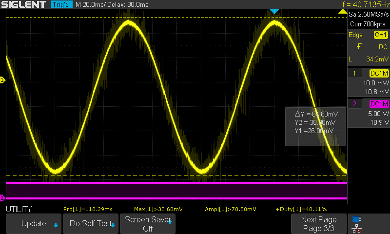
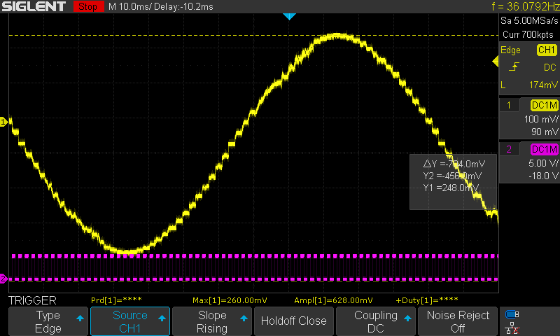
Phase A (BAD):
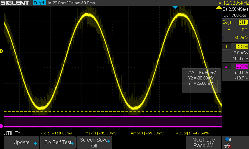
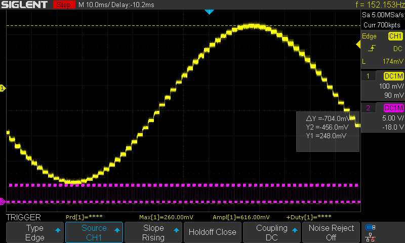
Phase B (OK):
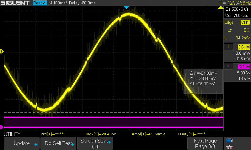
The issue becomes more noticeable at higher uStepping resolutions. This is 1/256, Phase A again:

Any help/hints/guesses would be much appreciated.
Thanks,
Galen