Other Parts Discussed in Thread: TCA9517, , DRV2605
Hi,
The setup: See picture erm_board_setup.
I am using an arduino mega2560 to send the I2C that i transform from 5V to 3V using TCA9517. The VCC is at 3.3V (confirmed by measurements).
My code is as follows: (Note: The idea is to control the pwm output not in open loop but by setting the rtp register duty cycle and letting the drv2605L handle the PWM)
void setup(){
Serial.begin(9600);
delay(250); //wait for arduino
Wire.begin(); //setup I2C
drv.ratevolt(0x8E); //operating voltage of 3V
drv.clamp(0x99); //clamp voltage 3.3V
drv.Mode(0x07); //Set autocalibration mode
drv.go(); //Start calibration
while(bitRead(drv.readDRV2605L(GO_REG),0)); //wait for GO bit to clear
bool calibOK = bitRead(drv.readDRV2605L(STATUS_REG), 3);
if(!calibOK){
Serial.println("Calibration is successful.");
}else{
Serial.println("Calibration failed."); //This is the output i get
}
drv.cntrl2(0x75);//set unidirectionnal mode
drv.cntrl3(0x88);//set closed loop mode
drv.Mode(0x05);//mode RTP
drv.RTP(127);
}
Two main problems:
1 - The auto-calibration always fails
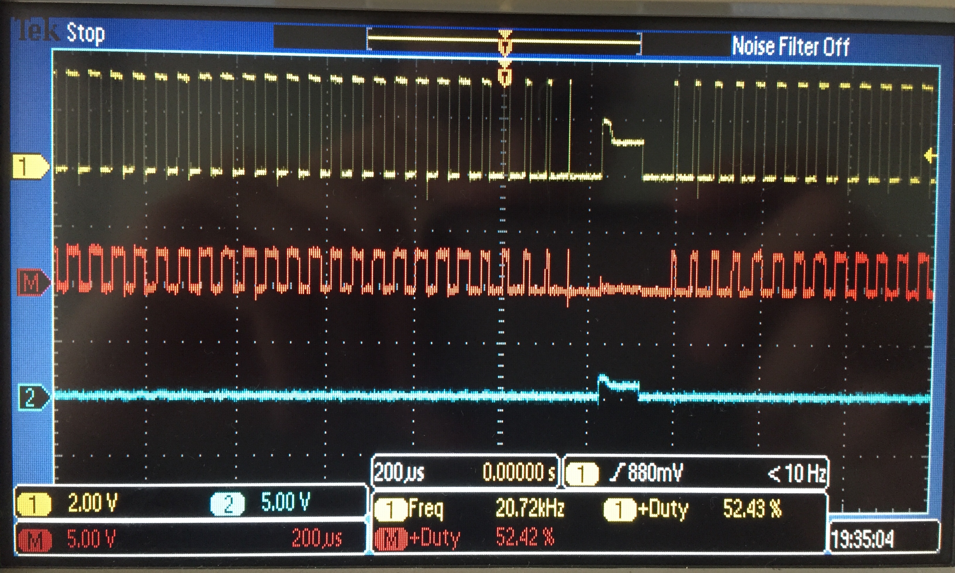
2 - The PWM output is 50% but there seems to be another signal overlapping. (See picture pwm _oscilloscope)

Thanks for the help