- Ask a related questionWhat is a related question?A related question is a question created from another question. When the related question is created, it will be automatically linked to the original question.
At start I read 2A register - default value is 0x018 but I read 0x08.
For a test purpose I write to the register 0x07
write 0x07 - read 0x03
write 0x0F - read 0x07
write 0x09 - read 0x00
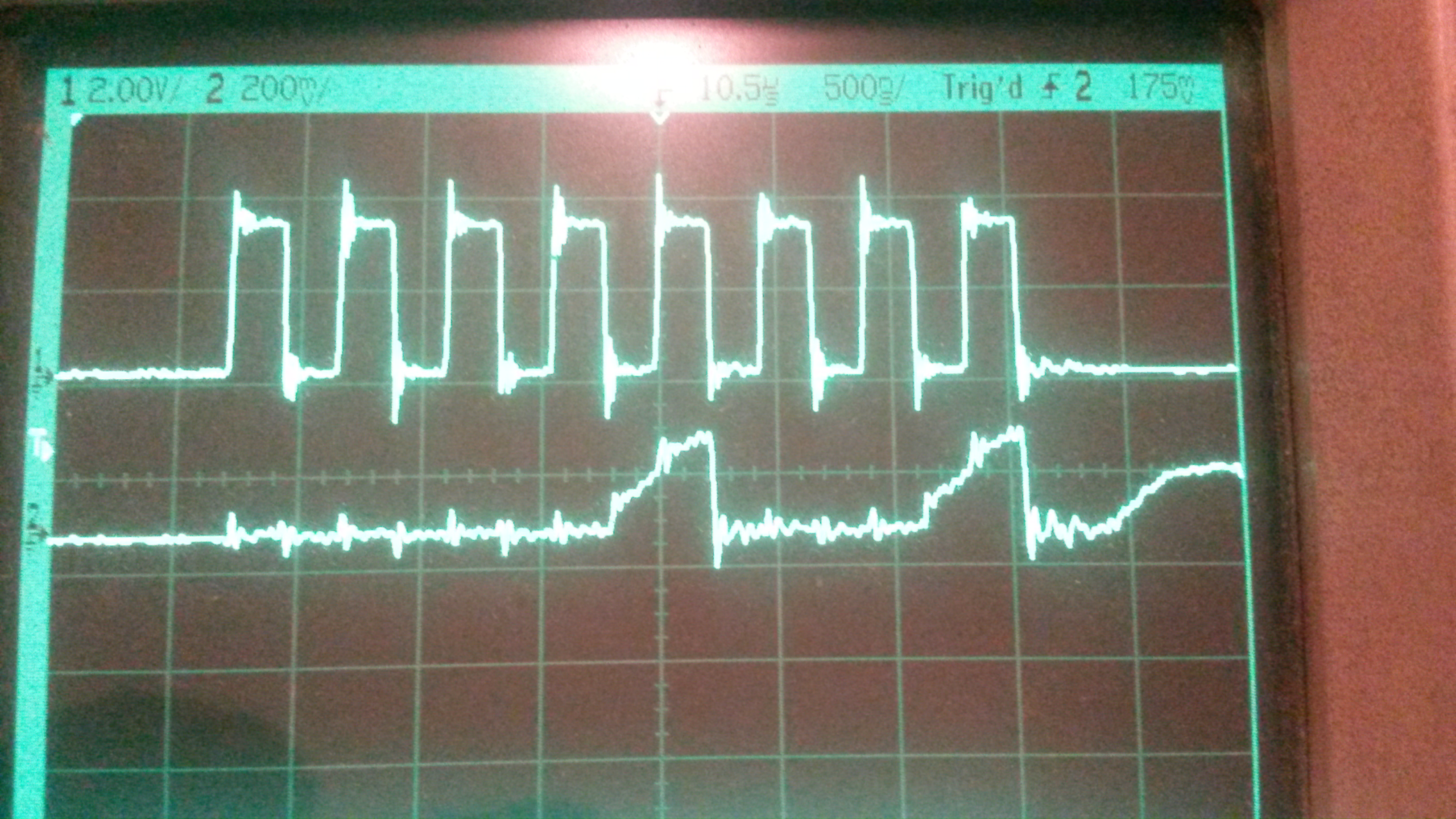
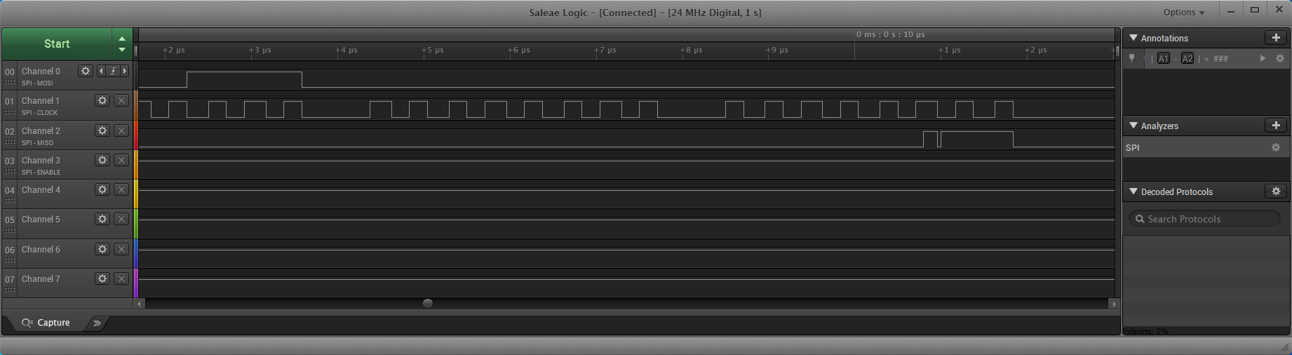
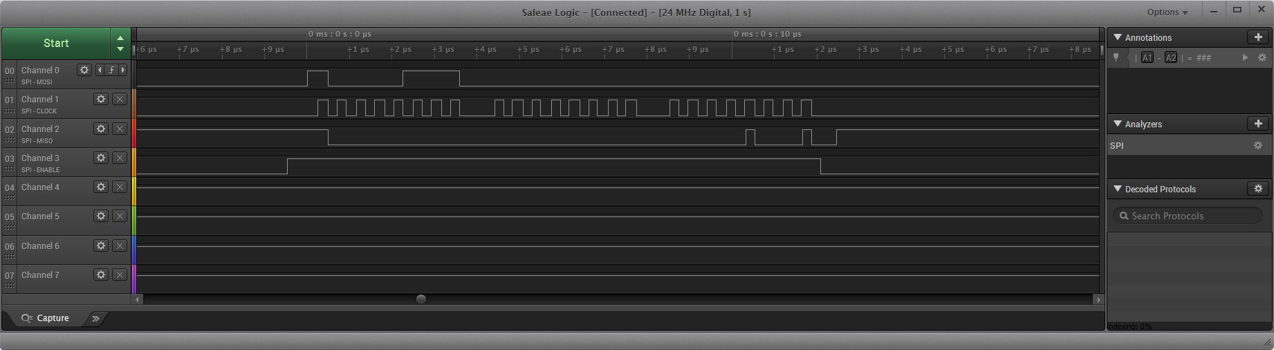
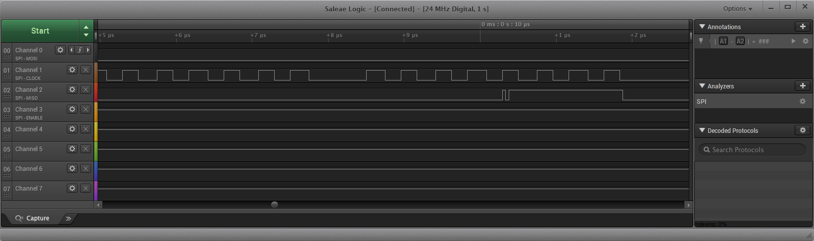
So I connected logic analizer and see all signals are good but data on SDATO pin is in phase with SCLK.
But data on the SDATO should be present on falling or rising edge of the SCLK.
This explains why the controller sees one bit less in case of 0111 (0x07) and 1111 (0x0F)
and dosen't see say 0x09 - separated bits.
I have a pull up 10K on SDATO pin.
How should I fix the problem?