- Ask a related questionWhat is a related question?A related question is a question created from another question. When the related question is created, it will be automatically linked to the original question.
Original question:

Tool/software: Code Composer Studio
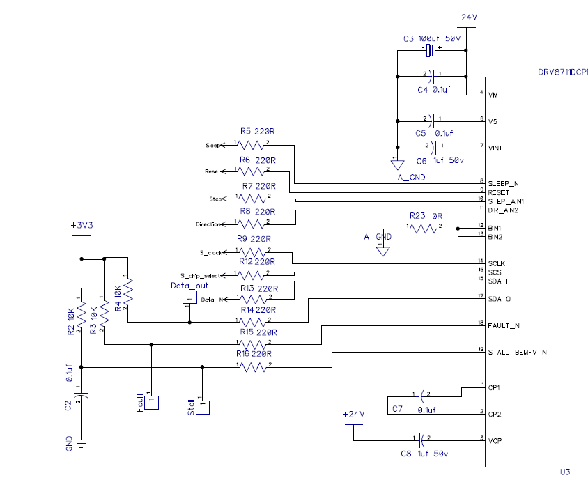
Im using this drv8711 with mspg2553.
This PCB is not working,
If PSI enable write, it is disabled internally @ drv8711.
I tried continous write drv8711 registers, motor slightly vibrates.
Parameters follows,
G_CTRL_REG.Address = 0x00;
G_CTRL_REG.DTIME = 0x03;
G_CTRL_REG.ISGAIN = 0x03;
G_CTRL_REG.EXSTALL = 0x00;
G_CTRL_REG.MODE = 0x03;
G_CTRL_REG.RSTEP = 0x00;
G_CTRL_REG.RDIR = 0x00;
G_CTRL_REG.ENBL = 0x01;
// TORQUE Register
G_TORQUE_REG.Address = 0x01;
G_TORQUE_REG.SIMPLTH = 0x00;
G_TORQUE_REG.TORQUE = 0xBA;
// OFF Register
G_OFF_REG.Address = 0x02;
G_OFF_REG.PWMMODE = 0x00;
G_OFF_REG.TOFF = 0x30;
// BLANK Register
G_BLANK_REG.Address = 0x03;
G_BLANK_REG.ABT = 0x01;
G_BLANK_REG.TBLANK = 0x08;
// DECAY Register.
G_DECAY_REG.Address = 0x04;
G_DECAY_REG.DECMOD = 0x03;
G_DECAY_REG.TDECAY = 0x10;
// STALL Register
G_STALL_REG.Address = 0x05;
G_STALL_REG.VDIV = 0x03;
G_STALL_REG.SDCNT = 0x03;
G_STALL_REG.SDTHR = 0x40;
// DRIVE Register
G_DRIVE_REG.Address = 0x06;
G_DRIVE_REG.IDRIVEP = 0x00;
G_DRIVE_REG.IDRIVEN = 0x00;
G_DRIVE_REG.TDRIVEP = 0x01;
G_DRIVE_REG.TDRIVEN = 0x01;
G_DRIVE_REG.OCPDEG = 0x01;
G_DRIVE_REG.OCPTH = 0x01;
// STATUS Register
G_STATUS_REG.Address = 0x07;
G_STATUS_REG.STDLAT = 0x00;
G_STATUS_REG.STD = 0x00;
G_STATUS_REG.UVLO = 0x00;
G_STATUS_REG.BPDF = 0x00;
G_STATUS_REG.APDF = 0x00;
G_STATUS_REG.BOCP = 0x00;
G_STATUS_REG.AOCP = 0x00;
G_STATUS_REG.OTS = 0x00;
WriteAllRegisters();
all the MCU pins are verified working.
some problem with SPI communication and im using the SPI sample code for drv8711 booster firmware.
UCB0CTL1 = UCSWRST;
// 2)
P2DIR |= CS;
P2OUT &= ~CS;
P1SEL |= SCLK | SDATO | SDATI;
P1SEL2 |= SCLK | SDATO | SDATI;
// 3) 3-pin, 8-bit SPI master
UCB0CTL0 |= UCCKPH | UCMSB | UCMST | UCSYNC;
UCB0CTL1 |= UCSSEL_2; // SMCLK
// 4)
UCB0CTL1 &= ~UCSWRST;
// End SPI Configure