This thread has been locked.

If you have a related question, please click the "Ask a related question" button in the top right corner. The newly created question will be automatically linked to this question.

DRV8332-HT: DRV8332-HT

Part Number: DRV8332-HT

We had a old sensorless BLDC design which used six discrete N-MOSFETs( IRF5NJ540) , one 3-Phase Driver IR2130D and three comparators. . The boot-strap capacitor of old design was 3.3uF. The PWM duty-cycle is 100%. The power supply of this BLDC is 50V. The current limitation of power supply is 1A. When current of 50V is greater than 1A, 50V will drop to around 10V. We are trying to replace the old design using DRV8332-HT, the boot-strap capacitor of new design  is 4.7uF.. The new design which use DRV8332-HT has start-up issue, but the old design does not have this issue.

Sensorless BLDC parameter: The resistance between phase to phase is around 12Ohm, the inductance is around 5.7mH. 

The motor control of old design is done by FPGA, for the new design, we just did the following conertion inside FPGA:: 

Suppose HOUT1,HOUT2, HOUT3, LOUT1, LOUT2,LOUT3 (active low) is six gate control signals for discrete MOSFET solution, the for DRV8332-HT, the logic of six control signals are:

PWM1= not HOUT1,

PWM2=not HOUT2,

PWM3=not HOUT3,

RESET1= '0' when HOUT1 ='1' and LOUT1='1' else

                 '1';

RESET2= '0' when HOUT2='1' and LOUT2='1' else

                 '1';

RESET3= '0' when HOUT3 ='1' and LOUT3='1' else

                 '1';

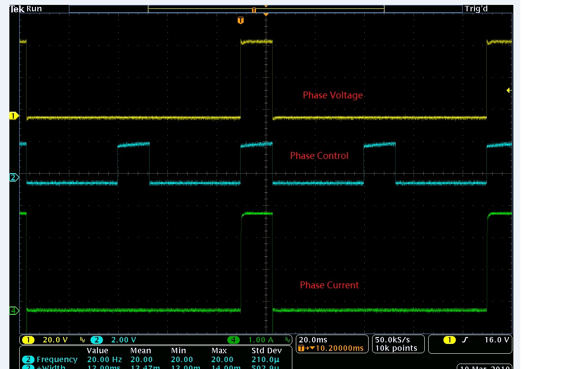
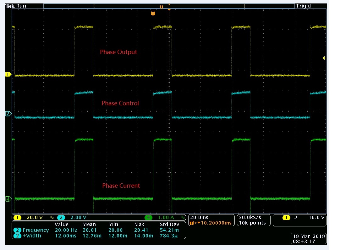
Each step (six-step) PWM is around 15ms when motor start-up for the old design, no alignment, no PWM ramp up.. We do not want to change control code now.

What is the possible reason for start-up issue of this new design? Why the old design can start, but the new design cannot ?

  • Hey Jimmy,

    How much off time is present in the design that is used to charge the bootstrap capacitors?

    Also, have you tried holding the RESET pins low during startup?

    What are the differences between the two designs?

    Thanks,

    Daniel

  • The only difference of two designs (the control is the same):

    • Old design uses six discrete MOSFETs, one 3-phase driver IR2130D.
    • New design uses integrate solution, use DRV8332-HT.

    I attached two test result. It appears that when the PWM width is more than 13ms, some output pulses will miss; when the PWM width is below 12ms, everything looks ok.

    I think this may be related to the pulse width. If the pulse width is too much, then the voltage across boot-strap capacitor will drop too much and hence cannot proper control 

    the high side MOSFET.

    I think there may be two solutions,:

    • Insert a 100ns low pulse for every 5ms PWM pulse  if the pulse width is greater than 5ms;
    • Increase the boot-strap capacitor's value (now is 4.7uF).

    Do you have any suggestions to solve the issue?

    In our application, the pulse width when start-up can be as high as 32ms,  the period is around 50ms.

    Your help is very appreciated!

  • Hey Jimmy,

    I would suggest trying to increase the size of the bootstrap capacitor.

    I didn't realize you were switching so slow with the device.

    The device is generally used for 10 kHz to 500 kHz, so running at 20 Hz is not going to be ideal.

    Trying to get the boot strap capacitor fix working seems worth trying before adding complexity to the signals.

    Thanks,

    Daniel

  • Daniel
    By "Insert a 200ns low pulse for every 5ms PWM pulse if the pulse width is greater than 5ms" solved the issue.

    I agree with you, increase the boot-strap capacitance value can also solve the issue, but our board space is limited and no pace for extra caps.

    Best regards,
    Jimmy
  • We had a failure of DRV8332HDDV recently at high temperature(390F). At room temperature, it was fine. It was found that PVDD was short to ground. The over-current resistor is 75kOhm, so the over-current limit is around 3.5A.  The power supply is 50V, The motor winding resistance is 12Ohm, the inductance is 6.7mH. the only reason I can think is Low-side MOSFET and High-side MOSFET of DRV8332HDDV conducts at the same time, so a big current flowed through Low-side and high-side MOSFET, hence caused the short. The boot-strap capacitor is 4.7uH(X8R), there is a 10Ohm resistor in serial with GVDD(12.8V)..

    Is the failure due to boot-strap under voltage so that cannot properly control High-side MOSFET and caused the failure? Normally what could cause PVDD short to ground for DRV8332HDDV?

    Your help is very appreciated!


  • Hey Jimmy,

    The maximum operating temperature is 185 C which is lower than the ~200 C you are testing at.

    I also assume you are likely doing ~200 C ambient which means our device will heat up over that 200 as well.

    This means the device failed outside its abs max range.

    I cannot comment on operation outside the abs max range.

    Thanks,

    Daniel