This thread has been locked.

If you have a related question, please click the "Ask a related question" button in the top right corner. The newly created question will be automatically linked to this question.

DRV2605: DRV2605 Auto-calibration issues

Part Number: DRV2605

Dear ti:

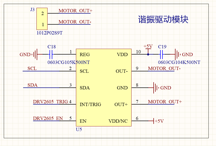
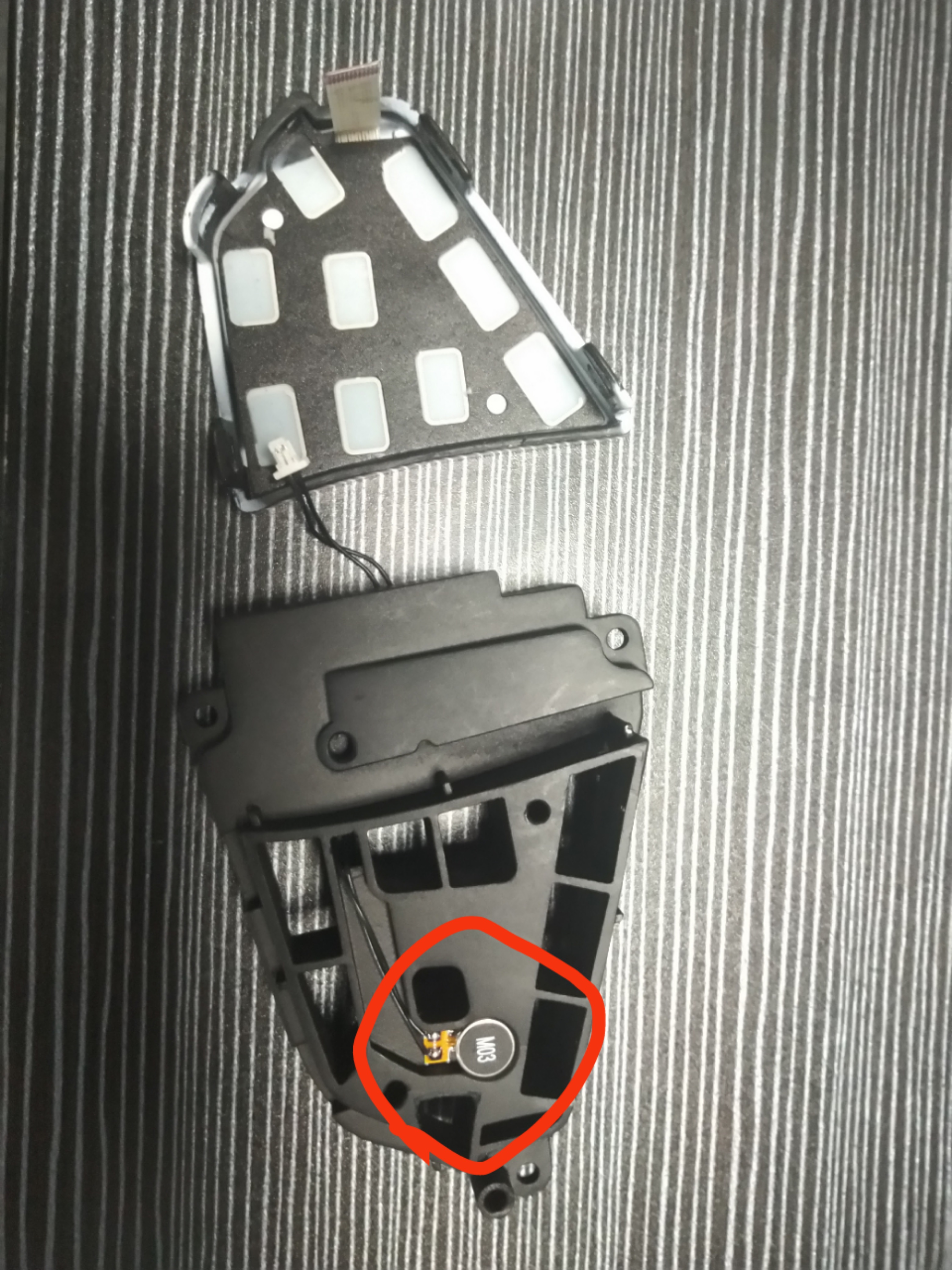
my custom use drv2605 as The steering wheel touch switch,  the motor is LRA ,Spec. as follow:
LRA规格.pdf


but when i use  auto-calibration ,  after initialization vibration cannot close on its own.
the return valve is:


May i know which register can closed its own function. thanks.

  • Hi,

    Could you provide additional details about this issue?

    Could you provide the circuit schematic? Also, is the LRA load attached or glued to a mass? It is important to glue the LRA to a mass (usually we use a 100g metal block). Otherwise, there could be issues with the auto-calibration.

    In addition, the LRA pdf doesn't contain details about the resonance frequency. Do you have these details too?

    Best regards,
    Luis Fernando Rodríguez S.
  • Hi,

    Do you have any feedback on this?

    Best regards,
    Luis Fernando Rodríguez S.
  • Dear ti:

    Update .thanks 

    waveform:

    0602.Waveform.docx

    configuration tools:

    5483.DRV2604 and DRV2605 Configuration Tool and Design Equations - LRA.xlsx

     Sch.

    Installation method:Above is the panel, the lower is the case. The motor is embedded in the casing and then the panel covered.

  • Hi,

    Excuse me, could you tell me which value you read in register 0x00 after the auto-calibration procedure?

    DIAG_RESULT flag (bit 3) shows if the auto-calibration routine is correct or not.

    Best regards,
    Luis Fernando Rodríguez S.
  • Hi,

    Excuse me, could you take a look at my last response?

    Do you have any update on this?

    Best regards,
    Luis Fernando Rodríguez S.
  • Hi,

    I will close this e2e thread for now, but feel free to comment about this issue in case you have additional observations.

    We will be glad to help you.

    Best regards,
    Luis Fernando Rodríguez S.
  • Dear Luis:

    sorry for the delay.   the value in register 0x00 after the auto-calibration procedure.

               left motor:          right motor:
    0x00:     0xb4      0xe0
    0x18     0xB4      0x07
    0x19      0xB4     0xB6

    left motor:

    right side:

  • Hi,

    Thank you for providing the information above.

    Could you try configuring the device with the following registers settings, please?

    These settings are normally used to set the auto calibration in the DRV2605x.

    Exported at :5/13/2019 10:37:21 AM
    	========Register Dump Start========
    		Reg:[0x0]	=	0xe0		Status
    		Reg:[0x1]	=	0x7		Mode
    		Reg:[0x2]	=	0x0		Real-Time Playback Input
    		Reg:[0x3]	=	0x6		Library Selection
    		Reg:[0x4]	=	0x1b		Waveform Sequencer 1
    		Reg:[0x5]	=	0x0		Waveform Sequencer 2
    		Reg:[0x6]	=	0x0		Waveform Sequencer 3
    		Reg:[0x7]	=	0x0		Waveform Sequencer 4
    		Reg:[0x8]	=	0x0		Waveform Sequencer 5
    		Reg:[0x9]	=	0x0		Waveform Sequencer 6
    		Reg:[0xa]	=	0x0		Waveform Sequencer 7
    		Reg:[0xb]	=	0x0		Waveform Sequencer 8
    		Reg:[0xc]	=	0x01		GO
    		Reg:[0xd]	=	0x0		OverDrive Time Offset
    		Reg:[0xe]	=	0x0		Sustain Time Offset, Positive
    		Reg:[0xf]	=	0x0		Sustain Time Offset, Negative
    		Reg:[0x10]	=	0x0		Break Time Offset
    		Reg:[0x11]	=	0x5		Audio-to-Vibe Control
    		Reg:[0x12]	=	0x19		Audio-to-Vibe Minimum Input Level
    		Reg:[0x13]	=	0x64		Audio-to-Vibe Maximum Input Level
    		Reg:[0x14]	=	0x19		Audio-to-Vibe Minimum Output Drive
    		Reg:[0x15]	=	0xff		Audio-to-Vibe Maximum Output Drive
    		Reg:[0x16]	=	0x3d		Rated Voltage
    		Reg:[0x17]	=	0xaa		Overdrive Clamp Voltage
    		Reg:[0x18]	=	0x6		Auto Calibration Compensation Result
    		Reg:[0x19]	=	0xc6		Auto Calibration Back-EMF Result
    		Reg:[0x1a]	=	0xa6		Feedback Control
    		Reg:[0x1b]	=	0x93		Control1
    		Reg:[0x1c]	=	0xf5		Control2
    		Reg:[0x1d]	=	0x80		Control3
    		Reg:[0x1e]	=	0x20		Control4
    		Reg:[0x1f]	=	0x40		Control5
    		Reg:[0x20]	=	0x30		LRA Open Loop Period
    		Reg:[0x21]	=	0xce		VBAT Voltage Monitor
    		Reg:[0x22]	=	0x3c		LRA Resonance Period
    	========Register Dump End========
    

    Please let me know your results and observations on this.

    Best regards,
    Luis Fernando Rodríguez S.

  • Hi,

    Do you have any response on this? Could you try the settings above?

    Best regards,
    Luis Fernando Rodríguez S.
  • Dear TI,
    We want to know whether the DRV2605 can output the wave in custom, rather than in using library.

  • Hi, Yuexin,

    Welcome to E2E and thank you for your interest in our products!

    The DRV2605 features an analog input mode which can be used to send a customized waveform. The amplitude of the input determines the amplitude of the output waveform:

    www.ti.com/.../drv2605.pdf

    I hope this helps you. Please let me know if you have additional questions or comments. I also suggest to start a new E2E thread in order to separate your questions from the actual threads and avoid confusion in case the threads are opened again.

    Thank you!

    Best regards,
    Luis Fernando Rodríguez S.