This thread has been locked.

If you have a related question, please click the "Ask a related question" button in the top right corner. The newly created question will be automatically linked to this question.

DRV8802: Usage of winding current

Part Number: DRV8802

Hi, I'm trying to use the DRV8802PWPR with the MSP-EXP430G2 launchpad.

I'm just controlling two DC motors. Since DRV8802PWPR has two outputs, this is perfect for me.

I got some questions.

Q0. Difference between -Q1 products.

I have purchased the DRV8802PWPR from Digikey. Whereas I saw DRV8802QPWPRQ1, which has Q1, is also sold. What is the difference between these two?

Q1. App example

For my case, I only need to control the speed and direction of each motor.

I'm trying to connect 2MHz 15% duty cycle PWM signal on AENBL pin and BENBL pin to control the output duty cycle.

Can AENBL pin and BENBL pin respond to MHz range on/off signals? I cannot find the pin's response from the datasheet.

Q2. I'm having a problem understanding the "Reference voltage for winding current set."

What are a winding current and current chopping?

Q3. ISEN - Connect to current sense resistor for bridge A/B

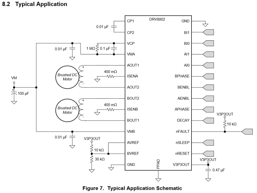
Why did the above application use a voltage divider for the reference? I'm confused with what reference I should provide.

For my case, I want to limit the current to 400mA for both outputs.

  • Hi David,

    Q0. Difference between -Q1 products.

    The DRV8802 and DRV8802-Q1 devices are very similar. The operating ambient temperature of the -Q1 product is higher than the non -Q1 device.

    Q1. Can AENBL pin and BENBL pin respond to MHz range on/off signals? I cannot find the pin's response from the datasheet.

    The maximum input frequency should be less than 100kHz. Most brushed motors are PWM'ed below 50kHz.

    Q2. I'm having a problem understanding the "Reference voltage for winding current set." What are a winding current and current chopping?

    During startup and stall conditions, the maximum current through the motor winding can be as high as VM/motor winding resistance. Current chopping limits the current through the motor winding. This is described in section 7.4.2 of the datasheet.

    Q3. ISEN - Connect to current sense resistor for bridge A/B

    Why did the above application use a voltage divider for the reference? I'm confused with what reference I should provide.

    For my case, I want to limit the current to 400mA for both outputs.

    The VREF input and current sense resistors are used to set the maximum current through the motor winding.  For a 400mA limit, there are many Ix/VREF/Risense combinations that can achieve. A good starting point is a 500mOhm resistor and a VREF of 1V with both I0 and I1 set to '0'.

    Please refer to Figure 5 for details. Equation 1 does not include the current scaling explained in section 7.4.2

  • Thanks for your help, Rick!

    Rick Duncan said:
    The maximum input frequency should be less than 100kHz. Most brushed motors are PWM'ed below 50kHz.

    Q0. May I ask the minimum input frequency as well?

    My team is trying to test the audible motor sound when running. I hope this video can give you an explanation.

    Check 4:51 from the video. BTW, I don't know the official technical term for this sound/noise.

    Do you know what is called and does TI has application notes for this?

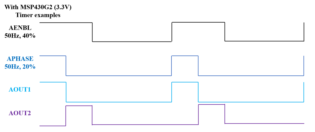
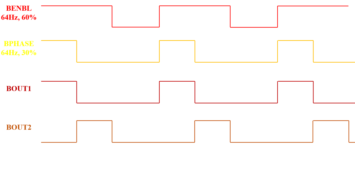
    Q1. If I feed the inputs like the above diagram, will the output be like that as well?

    As you see, I'm trying to make the motor turn clockwise/counter clockwise when the H-Bridge is enabled. I referred "Table 1".

    Hope it works on low frequency as well. We will test all the way to 10 Hz when VM = 20 ~ 40V.

    Q2. V3P3OUT will give 3.3V output. Do I have to connect this with MSP430's VCC in order to read the nRESET/nFAULT pin via GPIO interrupt? Or do I only have to tie both to the same GND?

    Q3.

    Rick Duncan said:
    For a 400mA limit, there are many Ix/VREF/Risense combinations that can achieve. A good starting point is a 500mOhm resistor and a VREF of 1V with both I0 and I1 set to '0'.

    You mean

    400mA = 1V / (5 * 0.5Ω)

    ?

    Q4. For AVREF and BVREF pins, if I don't want to create a voltage divider circuit, can I directly connect V3P3OUT to both AVREF and BVREF?

    Q5. If I don't want to limit the currents, can I just leave

    ISENA, ISENB, AVREF, BVREF

    as floating pins? Or, at least I have to connect some pins to GND?

    Thanks for your help!

  • Hi David,

    Q0. May I ask the minimum input frequency as well?


    There is no minimum. The inputs can be driven at 100% (no PWM).

    As noted in the video, if PWM'ing it is recommended to use a PWM frequency above 20kHz. This avoids the audible range.

    Q1. If I feed the inputs like the above diagram, will the output be like that as well?


    If by "above diagram" you mean the timer examples, the device output will match the timer examples if the DECAY mode is set to slow. If the DECAY mode is set to FAST, it will not. Please follow the note in Table 1 to the Decay and Braking Mode section of the datasheet. 

    As you see, I'm trying to make the motor turn clockwise/counter clockwise when the H-Bridge is enabled. I referred "Table 1".

    Hope it works on low frequency as well. We will test all the way to 10 Hz when VM = 20 ~ 40V.


    Q2. V3P3OUT will give 3.3V output. Do I have to connect this with MSP430's VCC in order to read the nRESET/nFAULT pin via GPIO interrupt? Or do I only have to tie both to the same GND?

    No, do not connect V3P3OUT to the MSP430 VCC. V3P3OUT is intended to power the internal logic of the DRV8802 and can be used to provide the VREF voltage and pullup the nFAULT pin.

    The grounds need to be connected.

    Q3.

    For a 400mA limit, there are many Ix/VREF/Risense combinations that can achieve. A good starting point is a 500mOhm resistor and a VREF of 1V with both I0 and I1 set to '0'.

    You mean

    400mA = 1V / (5 * 0.5Ω)

    ?


    Yes, that is correct.


    Q5. If I don't want to limit the currents, can I just leave

    ISENA, ISENB, AVREF, BVREF

    as floating pins? Or, at least I have to connect some pins to GND?


    If you do not want current limits, connect ISENA/ISENB to GND and AVREF/BVREF to V3P3OUT. ISENA/ISENB are needed to complete the current path and AVREF/BVREF are set to prevent current chopping. Refer to the functional block diagram.