This thread has been locked.

If you have a related question, please click the "Ask a related question" button in the top right corner. The newly created question will be automatically linked to this question.

DRV8806: DRV8806 controls solenoid valve enters protection mode

Part Number: DRV8806
Other Parts Discussed in Thread: LM2675, DRV8860, DRV8886

Hi Team,

Now, DRV8806 is used as the control solenoid valve. We can control OUT to output VM and GND to achieve control. OUT can normally control the value of OUT with no load or resistance connected. When connected with solenoid valve, it will enter a protective state and nFAULT is set to 0. However, the manual says that the protective state will only occur under situation of under-voltage, over-current and over-temperature. So what are the possible problems? I expect to hear your opinions. Thank you!

  • Hi Annie,

    As you pointed out, the nFAULT is an indication of either an undervoltage, overcurrent, or overtemperature event.

    nFAULT can be used to determine the most like type of fault by using a scope to measure the time between nFAULT asserting (set to 0) and nFAULT de-asserting (set to 1).

    For overcurrent, the nFAULT assertion time is approximately 1.2ms
    For overtemperature, the nFAULT time will be much longer but varies
    For undervoltage, the nFAULT time also varies but VM can be monitored at the input of the device.
  • Hi Rick,

    Thanks for your answer.

    VM has no obvious changes, so it should not be undervoltage.
    For over temperature, customer has not measured the time. But the moment of control is directly into the protection, the chip has no obvious temperature change.
    And software reset can't be solved and it has not worked normally.

    In addition, controlling the resistive load, or controlling the Peltier, can be normal, and the inductive load is not normal. According to the manual, the chip has no peripheral design, and it only needs to be connected directly to the load to work normally. Customer would like to know what should the DRV8806 need to pay attention to when connecting to the inductive load?

    Thanks.
  • Hi Annie,

    In your response, you said " But the moment of control is directly into the protection, the chip has no obvious temperature change." If this means nFAULT is set within a few us of enabling the output, the fault is probably overcurrent.

    Please ask the customer to provide a scope capture of the time between nFAULT going low and nFAULT going high. This information will help determine if the fault is overcurrent or overtemperature.

    Also, if the customer has a current probe, please provide a scope capture of the current when the output is enabled.
  • Hi Rick,

    When the solenoid valve is connected, (Observe through an oscill)

    • Start output, the time from high to low level of nFAULT is about 400us.
    • Turn off the output, it will return to high level from low level in about 4ms.

    The customer uses a multimeter to measure the current, and the maximum current does not exceed 1.2A. Is there any suggestion to resolve this problem? The customer tried a string of 100uh inductors, but the problem was not solved.

    Thanks.

  • Hi Rick,

    The customer found that the solenoid valve was connected to an energy-saving module. After he removed it, it was normal. It can be speculated that it should be an overcurrent problem.

    Is there any suggestion how to resolve this issue?

    Thanks.

  • Hi Annie,

    Thank you for the additional information.

    Using a DMM to measure the current does not provide enough information. DMMs typically measure average current. An overcurrent event occurs in a few microseconds. That is why a current probe is important.

    The delay of 400us from starting the output to nFAULT may also indicate overtemperature.

    What is the time from nFAULT going low to nFAULT going high? If the nFAULT takes more than 1.2ms, this may be an overtemperature event.

    What is an energy saving module? Can you provide a part number or schematic of the energy saving module?

    Once we are able to determine if the event is overcurrent or overtemperature, we can suggest a solution. 

  • Hi Rick,

    It will return to a high level from low level in about 4ms. If you follow your statement, is it overtemperature?

    Additionally, if the solenoid valve is controlled by OUT1, the other OUTx except OUT1 can work normally as long as the solenoid valve is not connected.

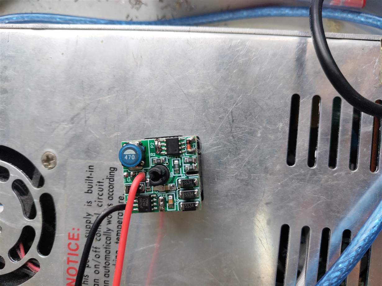
    The energy saving module is purchased from the Internet together with the solenoid valve. He can only see the chips and components used. It used TI's LM2675 regulator chip, and the other chip seems to be a MOS (Chip top side marking I RP715D 7B6E F7240). There are two capacitors on the back, 47uf / 35V and 100uf / 35V.

  • Hi Annie,

    It is difficult to confirm overtemperature based on the information.

    Can you provide a schematic of how the DRV8806 connects to these modules?

    Also, please provide the link to the energy saver module with solenoid.

    The schematic and link can be sent to me via private message.

  • Hi Annie,

    Thank you for the additional information.

    Unfortunately, I need some more.

    What is connected to the points J16A:D to J19A:D? In addition to what is shown in the schematic are thes points connected to the pinch solenoid or the energy saver module?

    What is the value of the bulk capacitors shown?

    How are the solenoids controlled?
        Are the solenoids energized for some short time, then the energy saver module is enabled?
        If yes, how long are the solenoids energized?
        How long are the energy saving modules energized?

    How well is the DRV8806 connected to the PCB? If the thermal connection is marginal, the device could experience overtemperature. If possible, please send the layout of the PCB.

    FYI -- The DRV8860 or DRV8860A may be an alternative. These devices can be programmed to drive the solenoid at 100%, then reduce the power after some time. This may eliminate the need for the energy saving module.

  • Hi Rick,

    1. They can be connected directly, solenoid valve and energy saving module are combined. That is to say, when there is an energy-saving module, it directly connects the energy-saving module and connects the solenoid valve through the energy-saving module. And when there is no energy saving module, it directly connects the solenoid valve. (It is normal when connected directly. But after the power is on for a long time, the solenoid valve is hot. I think about whether I can add energy-saving modules.)

    2. the value of the bulk capacitors: 100uf/50V

    3. layout of the PCB: I have sent it to you via private message.

    The solenoid valve directly controls the DRV8806 to outputs a low level. This causes a differential pressure circuit between the solenoid valves. There is no special control.
    When the customer tests, he only takes about 15 minutes when the solenoid valve is connected, and the solenoid valve is already hot. Then, he did not continue to test. The customer is not very know clearly about the energy-saving module, the seller only said that direct power supply would be fine. Customer follows this way and it is normal.

  • Hi Annie,

    I think I understand the connections.

    With the energy saving module:

       DRV8806 ---> Energy Saving Module Negative wire

       Energy saver positive output ---> Solenoid Valve positive connection

       Energy saver negative output ---> Solenoid Valve negative connection

       So the solenoid does not have a direct connection to the DRV8806

    Without the energy saving module:

       DRV8806  ---> Solenoid Valve Negative wire

    Is the above description correct?

    "The seller only said that direct power supply would be fine." The DRV8806 is not a direct power supply.
    The DRV8886 can overheat if too much current is required for too long and the thermal connection to the PCB is not sufficient. This may be part of the problem.

    If possible, please ask the customer to provide:

    1) a scope capture of the current from energizing the energy saver to the nFAULT.

    2) a scope capture of the current from energizing the soleniod to the time of the nFAULT above.

    It is possible the energy saver plus solenoid initially requires more current and is causing the overheating.

    Thank you for the layout. I have the following comments:

    1) The vias under the DRV8806 are too large. They are 20mils. The recommended size is 7.874 mils. This is to prevent solder wicking.

    2) There does not appear to be a large thermal area on the bottom of the PCB. Depending on how many outputs are energized. This could be an issue over time. Please ask the customer to consider filling the bottom layer with PGND to provide more thermal relief.