This thread has been locked.

If you have a related question, please click the "Ask a related question" button in the top right corner. The newly created question will be automatically linked to this question.

DRV8821: Stepper motor backfeeding DRV8821?

Part Number: DRV8821
Other Parts Discussed in Thread: DRV8885, DRV8880, DRV8886

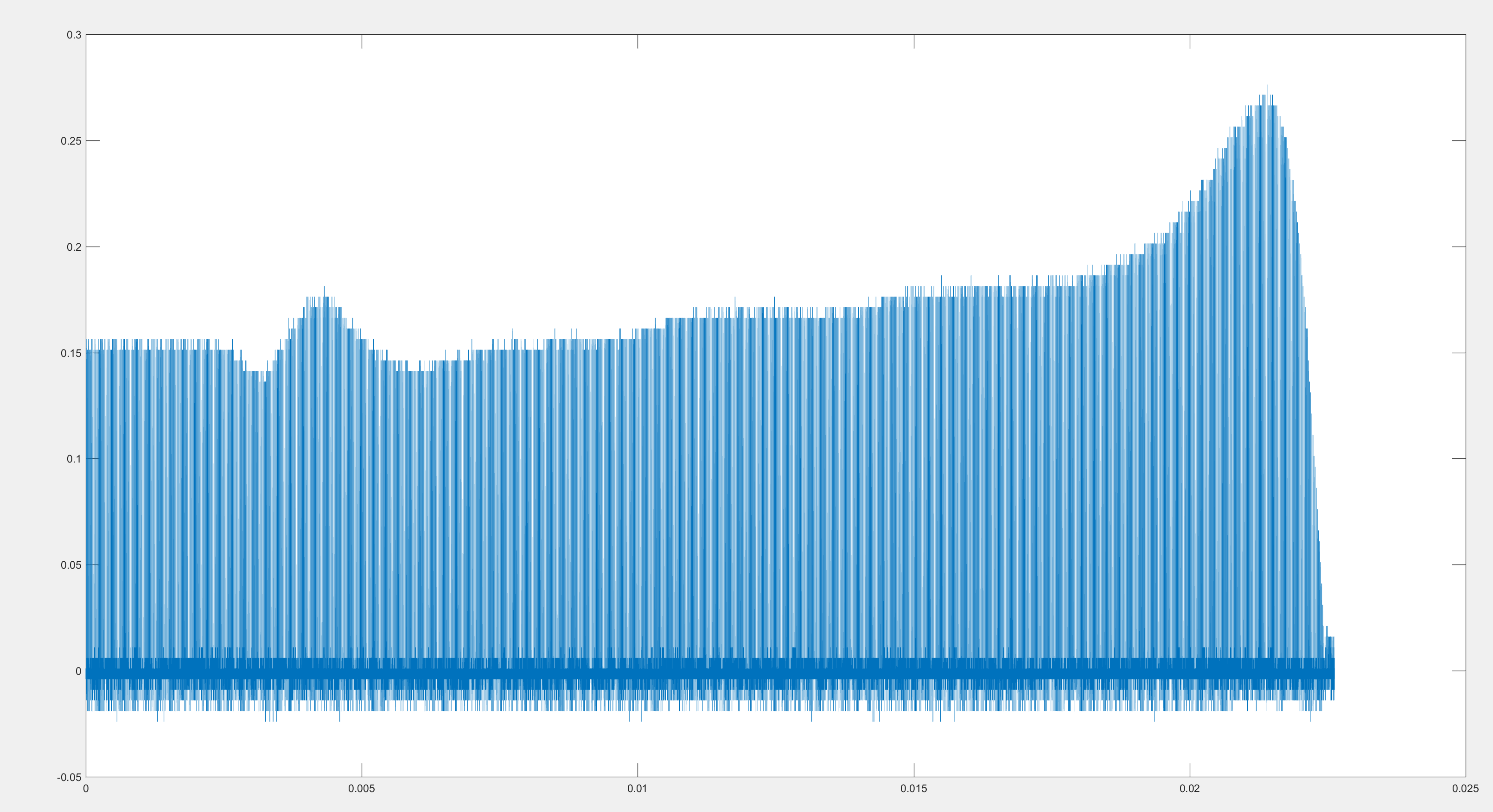
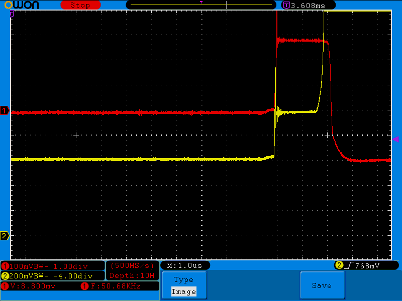
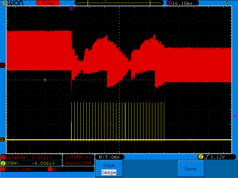
I have a DRV8821 driving a stepper motor at 1 amp peak. If I grab the motor and force it to turn when it is energized and stationary, the motor de-energizes. Probing the current sense resistor shows the coil current rising above 1.5 amps, suggesting the over current protection is being tripped. The reference voltage appears stable. Supply voltage is 24 V, micro stepping is set to 8, and decay is mixed. If I don't touch the motor, the coil current is the expected value and the motor runs as expected. This problem does not appear if I use a smaller stepper motor. 

Is it possible for the stepper motor to backfeed the driver, triggering the over current protection? If not, why does the motor unlock?

Is the current regulation on the driver supposed to prevent this? If not, is there a circuit or driver that can?

  • Hi Rodney,

    What is the VREF voltage, DECAY setting, and sense resistor values?

    An overcurrent event should occur if the current is above the Iocp level for more than 2.5us. Are you seeing this?

    Can you provide a scope capture of the xISEN voltage when the fault occurs?

  • VREF is 0.75 V, DECAY is high (mixed), and sense resistor is 0.15 ohm.

    The current is above 1.5 amps, but the time seems to be slightly under 2.5us (typically about 2.3us).

    The exact area where the fault occurs is difficult to pinpoint, so I've included a plot of the general region.

  • Hi Rodney,

    Thank you for the additional information.

    If you have a 2 channel scope, a good method to capture the fault is to trigger on the fault. Place the trigger point toward the end of the display so the xISEN voltage can be observed prior to the fault.

    Zooming in to 1us/div will be helpful.

    Also can you provide a scope capture of the motor current on xISEN for a 32 steps (360 degrees electrical). Ideally please use a input STEP frequency of 1kHz and provide the STEP input and the xISEN voltage.

    The current should not exceed 1A as the motor is spinning, but please note slow decay is used as the current is increasing from 0 to 100% or 0 to -100%. During these steps, the current could exceed the 1A Ichop value. 

    A few more questions:

    1) Could this be an overemperature event? Do you have a good connection from the thermal pad to the ground plane of the PCB?
    2) Do you have two motors connected and energized? If so, can you disconnect (or disable) one motor to help rule out overtemperature?
    3) Can you confirm the VREF at the pin is 750mV and the sense resistor is 150mOhms? If confirmed, can you lower the VM voltage to 12V and confirm if the current is regulating as expected.

  • Unfortunately, the DRV8821 does not have dedicated fault pins unless I missed something in the datasheet. Such pins would also be useful in determining the type of fault. I also do not have a scope that can trigger on voltage over threshold for a fixed amount of time. I can only capture a rising edge, but ISEN rings above the threshold during normal operation.

    I attached a screenshot of where I believe the fault occurs, since I cannot see the bridges switching afterwards. Red line is ISEN, yellow line is a AOUT1.

    A zoomed out plot of ISEN is very noisy. Red line is ISEN, yellow line is STEP.

    I don't think this is an overtemperature event because the motor stays energized for hours without unlocking, but will unlock right away when forcefully turned right after power on. After an hour, the surface of the chip is about 60 C. I'm not sure about the connection to the thermal pad without having the board x-rayed.

    There is only one motor connected.

    I can confirm VREF is 750mV. I'm relying on the markings of the sensor resistor since I don't have equipment that can accurately measure less than 1 ohm. If I lower VM to 12V, it does not unlock. The current seems to only be 0.5 amp.

  • Hi Rodney,

    You are correct; there is no nFAULT pin on the DRV8821. My apologies.

    The following is my assessment based on the images and speculation about the xISEN voltages:

    The last image that you provided shows what looks like one half sine wave and some portion of a second one.

    Of interest is the current prior to the step pulses and current after the step pulses. The current prior to the step pulses appears to be higher than 1A (voltage appears to be >200mV. The current after the step pulse appears to be less than 1A (voltage appears to be ~120mV).

    The difference is prior to the step pulses may be slow decay and after the step pulses is probably mixed decay.

    Slow decay and high voltage can lead to loss of current regulation. Lowering the voltage or adding resistance can help mitigate this.

    Our newer stepper drivers like the DRV8880, DRV8885, and DRV8886 can limit this loss of current regulation. These devices have more decay modes including mixed decay when the current is increasing.

    You would need two of the devices to control two steppers.