A related question is a question created from another question. When the related question is created, it will be automatically linked to the original question.
If you have a related question, please click the "Ask a related question" button in the top right corner. The newly created question will be automatically linked to this question.
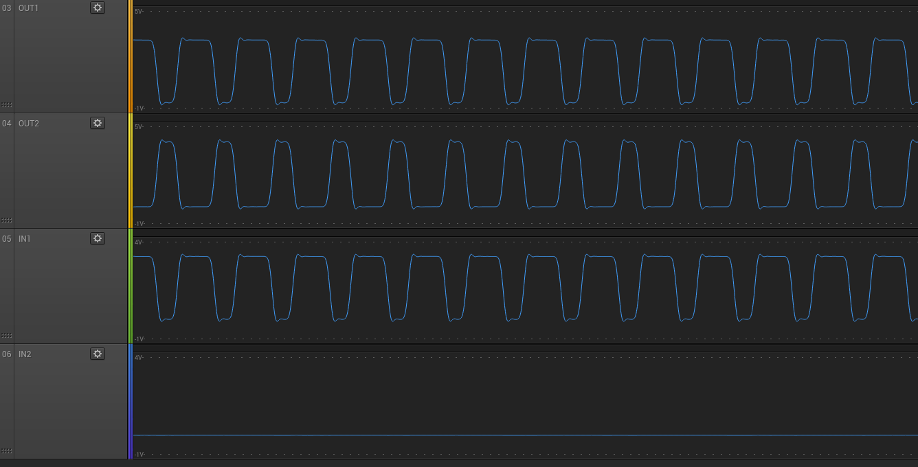
DRV8837C: Why OUT1 is the opposite of OUT2 when PWM is on IN1 and IN 2 to ground?
I am assuming you are asking why the OUT1/OUT2 do not enter the Z state when the PWM input is 0. Is that correct?
When IN1 transitions from 1 to 0, the outputs will be disabled as shown in Table 1. But if there is current flowing through the inductive load, the voltage on the outputs will switch from VCC to -0.7V or from GND to VCC+0.7V. This voltage is needed to maintain current flow through the load.
Once the current drops to zero, the two outputs may change.
> I am assuming you are asking why the OUT1/OUT2 do not enter the Z state when the PWM input is 0. Is that correct?
Yes
> When IN1 transitions from 1 to 0, the outputs will be disabled as shown in Table 1. But if there is current flowing through the inductive load, the voltage on the outputs will switch from VCC to -0.7V or from GND to VCC+0.7V. This voltage is needed to maintain current flow through the load.
Ok great I understand the behaviour
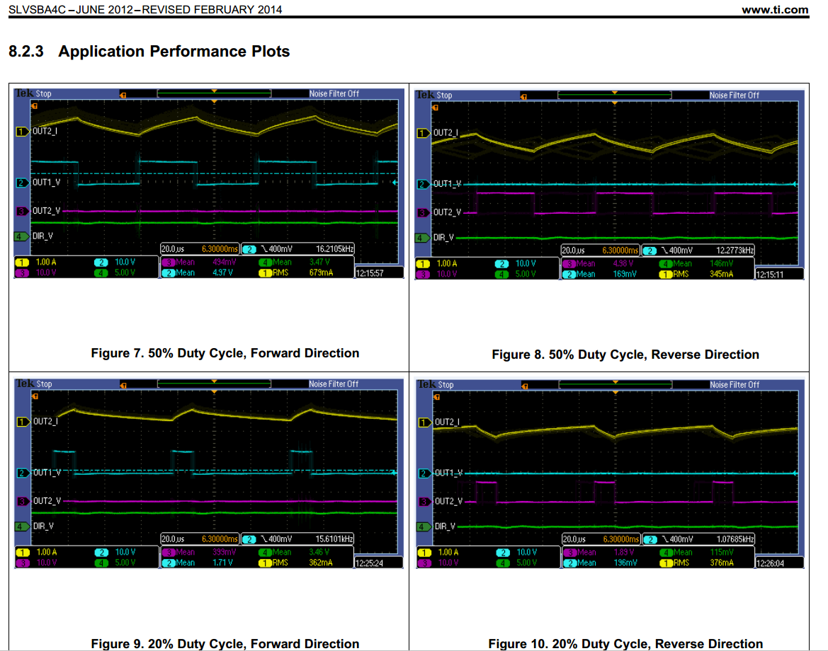
I asked that question because in the datasheet, the plots shows no PWM signal on OUT2 (Figure 7) and it seems that there is load (OUT2_I). Why is it different on datasheet graphs?
Figures 7 through 10 are using a different PWM scheme.
In your question, IN2 is held at GND. The outputs are toggling between Drive(Forward/Reverse) and Coast (Z)
In the figures above, the static input is held at 1. The outputs are toggling between Drive(Forward/Reverse) and Brake (both outputs low). Toggling between Drive and Brake typically provides more torque to the motor because the current decay is less in Brake mode.