This thread has been locked.

If you have a related question, please click the "Ask a related question" button in the top right corner. The newly created question will be automatically linked to this question.

DRV10970: Need details on how the internal boost works.

Part Number: DRV10970

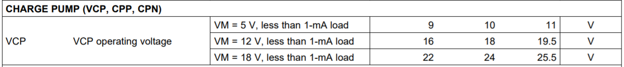
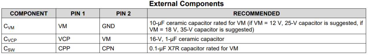
I'm submitting a design to UL, and they are asking for a description of how the voltage boost functions.  It appears to be a simple capacitor boost circuit, but they need more details to be sure how it might fail.  They need to find the worse case voltage it could boost under abnormal conditions.

  • Hi Jon,

    Thanks for posting your question in E2E forum. DRV10970 uses Charge pumps to boost voltage. If you look at the working principle of Charge pumps, it is a voltage doubler with two capacitors being switched to hold the supply voltage. Below table from the datasheet shows the Min, Typ and Max VCP voltage at different Vm.  I am assuming "Worst case voltage" means min Vm. If that's true, at Vm = 5V, the VCP voltage will be 11V max when the load current is less than 1 mA.

    Below table shows the recommended values for choosing the Capacitors based on Vm. 

    Let me know if you have any difficulty in viewing the images.

    Regards,

    Vishnu

  • Thanks for the reply.  UL has already looked at that, and they are asking for more details.  They want something that shows, or explains how it works.  The datasheet doesn't actually say the mechanism, and UL won't make any assumptions.  So I need something in writing from TI that give more details, so they can be sure that under a failure condition that the voltage could never be higher than that.

    Thanks,

    Jon

  • Hi Jon,

    I have forwarded your request to the team. Will get back to you once I hear from them. 

    Regards,

    Vishnu.