Hi,
I would like to test the DRV8353Rs-EVM-Board with ISO-F28027F. This board is connected with BLDC motor and is supplied with 60VDC / max. 3A. This Gate driver board worked very well with TI program DRV8353Rx 1.0.0. The parameters of motor are identified and the motor could run with speed control.
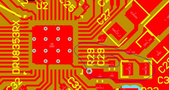
After that I wanted to change operating mode from “split rail” to “single rain” by replaced of resistor R19 and R18. Then I changed the LDO output from 12V (standard) to 5V by changing of resistor R29 (from 2,61k to 10k).
Now the motor can no longer be identified and controlled. The nFAULT-LED is lighting up. Based on the register report on program DRV8353Rx 1.0.0, I suspect the error is due to VCP- Charge pump under voltage. You can see these pictures of register report below.
I have also measured the voltages VM, Vcp, Vgls and Dvdd. Only the charge pump voltage Vcp is noticeable. This is 42,2V (VM+2V), although it’s supposed to be VM+10,5V as a recommendation.
I want to ask you, if I’ve done something wrong? Can you give me some helps to solve this problem?
Any helps will be appreciate!
Thanks for your attention,
Hoang