This thread has been locked.

If you have a related question, please click the "Ask a related question" button in the top right corner. The newly created question will be automatically linked to this question.

DRV2625: DRV2625 VDD current have negative

Part Number: DRV2625

Hi

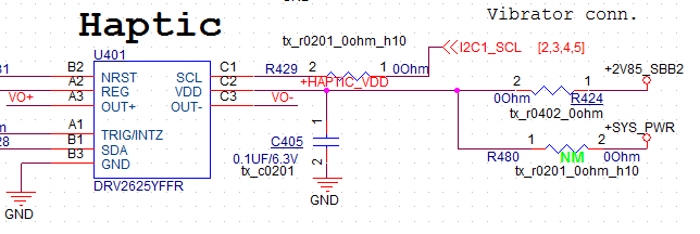
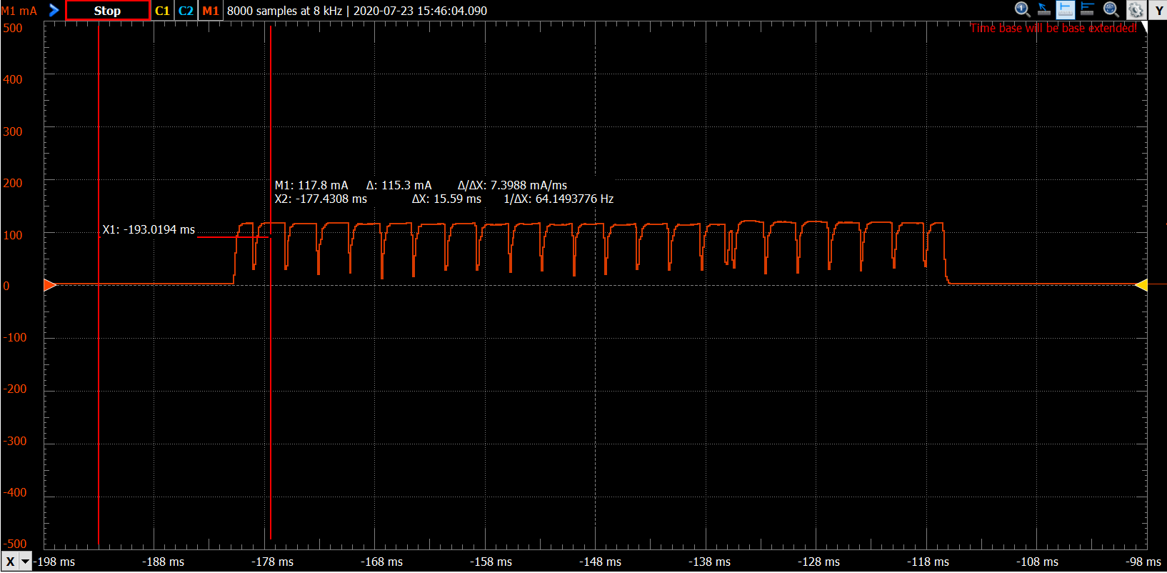
We check DRV2625 VDD current with driving LRA vibrator

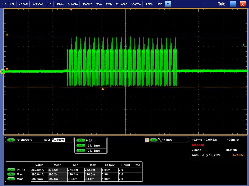
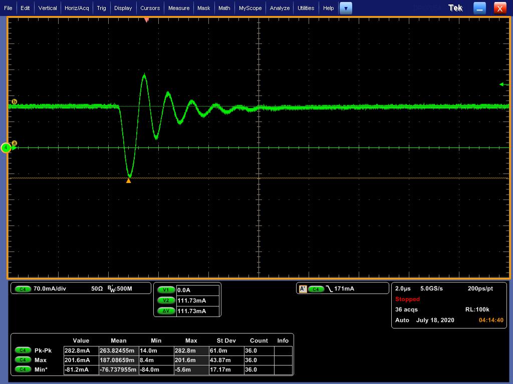
We fine there is negative current part when we using current probe to measure

Is it normal? If yes, how do we estimate VDD current? Using Vpp(pk-pk) or use Vp(max) ?

If no, do you know anything wrong?

Thank you~~

  • Hey Poki,

    I see your waveforms and understand what is being shown in the top image but could you explain what is the waveform in the bottom image.

    It is not normal for the DRV2625 VDD current to read negative values. Can you draw a diagram or show me the configuration of your measurement to make sure you are properly recording from the VDD pin. To properly measure current you would need to put the probe at the VDD pin and not at the output where the H-bridge has the current switching directions.

    Best,

    Carson Allen

    LPAA Applications

  • Hi Carson,

    1. The bottom image is the detail waveform (you can see time scale from 10ms to 2us)

    2. YES we use current probe to measure VDD pin, not OUT+/OUT-, we remove R424 resistor, jump wire from R424.1 and R424.2 pad, and use current probe measure current through this wire

    Poki

  • Hey Again Poki,

    I see your set-up but can you explain what is SYS_PWR vs +2V85_SBB2 and why you have both of those connected to the VDD via resistors?

    Best,

    Carson

  • Hi Carson,

    The SYS_PWR is reserve for another supply for DRV2625, we didn't mount R480 resistor so you don't need care about this

    Also we found that if LRA vibrator no fix well at object, the OUT+/OUT- waveform is not normal

    So will it cause current become negative?

    Thank you~~

    Poki

     e2e.ti.com/.../3416990

  • Hey Poki,

    The issue with it the LRA not being fixed affecting the waveform should not be affecting the current  to go negative at the VDD pin.

    I am going to perform a measurement of my own to determine what the current should look like, but can you tell the exact mode of operation and waveform you are playing so that I can set it up under the same conditions?

    Best,

    Carson

  • Hi Carson:

    We are using I2C to control, NRST is high no matter LRA vibrate or not, and waveform is Strong click-100%

    Thank you~~

    Poki

  • Hey Poki

    I went ahead and did my current measurement and yielded this plot,

    As you can see the current never goes negative and rests at a value of about 2.5 mA. This is what your plot should more or less look like.

    Can you take a measurement of the voltage & current waveforms of the output of the device that would correspond with the Vdd current waveform from above?

    Also are you using open or closed loop?

    Best,

    Carson

  • I am going to close this thread for now, but feel free to reply at anytime.

    Best,

    Carson Allen