This thread has been locked.

If you have a related question, please click the "Ask a related question" button in the top right corner. The newly created question will be automatically linked to this question.

DRV8301: DRV8301 can't run a brushless motor

Part Number: DRV8301

Hello,

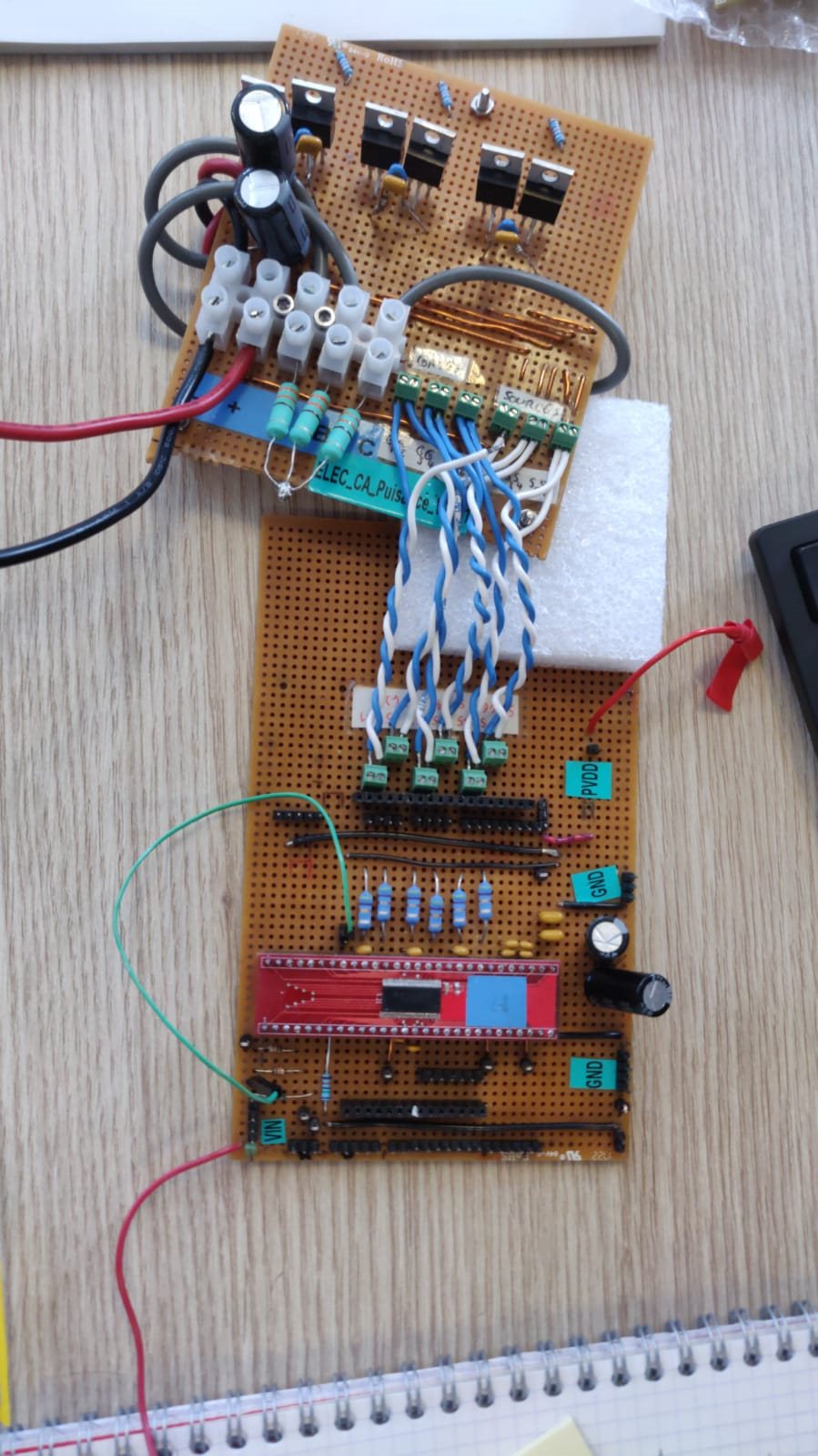
We are three students trying to run a brushless motor with the DRV8301 driver. We use a custom APS6355S motor with sensors (2200W, 190KV, 42V, 55A according to the manufacturer) and IRFB7546 MOSFETs (Vds 60V, Rds 6.0 mOhms, Id 75A). While our system works with simples resistances instead of the phases of the motor (goods signals), when we connect the motor, the motor refuses to move despite an audible wriggling. The driver suffers damage that we do not understand (we note an under-voltage on GVDD). We believe that our problem stems from a hardware configuration error or a wrong/bad realization of our prototype (development board with holes / copper strips).


Our servo procedure is as follows: we gradually increase the duty cycle of the PWM signals sent to the MOSFET gates and the microcontroller is responsible for sending the signals to the right gates according to the position of the motor (normally the algorithm is not the source of the problem). However, after increasing the duty cycle by a few percent, the driver went into error (nFault). We believe that the current draw of the motor when it is started is responsible for this result.

The peak current can go up to around 500A according to our calculations. The driver will therefore go to safety but will that prevent us from running it?

On the other hand, we have observed the presence of noise at a frequency of around 800MHz, the amplitude of which is quite variable, but we are not sure of its origin. By modifying the position of the ground point of our assembly we were able to partially solve this noise problem (less noise).

Is there an error in our assembly or our method? Do you have any specific advice for us?

You can find the entire assembly and the engine datasheet attached.

Thank you so much.

Schema_esc_V1.4.pdf

  • Hi  Thibaud,

    Thank you for posting your question on the MD forum! I will respond to your questions tomorrow. Sorry for the delay!

    Regards,

    Anthony

  • Hi Thibaud,

    I am glad you all have the opportunity to work with motor drivers! I have a few questions and comments:

    • Can you confirm that the hall sensors a-b-c of the motor are connected in the same order as the a-b-c of the phases?  If the corresponding hall sensors of the phases are in the wrong order that can cause the motor to not spin properly.
    • The CP1-CP2 capacitor is supposed to be 22nF, and I noticed you used two 10nF capacitors in parallel. I would highly recommend changing that to a single 22nF capacitor if possible.
    •  What are the capacitance values that are used on the BSTx pins?
    • What are the voltage ratings of the BSTx, GVDD and CP1-CP2 capacitors?
    • Is the driver and MOSFETs all on one board? Or are there multiple boards? Would you be able to provide a layout showing the DRV and the surrounding capacitors?
    • You mentioned that the peak current can go up to 500A. what calculations did you use to obtain this value?
      Regards,

      Anthony Lodi

  • Hi Anthony,

    The hall sensors of the motor are connected in the same order as the phases.

    We can't change this two 10nF capacitors right now.

    The capacitance values that are used on the BSTx pins are 0.1µF.

    The voltage rating are : BSTx = it depends of the motor phase. For one BST the voltage rating is 0V, for an other it is 0 to 36V slot signal (it depends of the PWM frequency), and the last one is 0 to 18 V slot signal (depends of the PWM frequency). GVDD = around 11V V, CP1-CP2 = we don't know, we hand't mesure it.

    Here is a picture of the boards. We are currently changing this. Now we have only one board.

    The intern resistance inside the motor is 0.07Ω. With 36V we obtain 514A at start-up. We also use a formula with Kv. Current draw = Torque * Kv and we obtain 550A.

    Regards,

    Thibaud Hemon.

  • Hi Thibaud,

    You mentioned that you are working on a single board solution, so I think it would be best to complete that single board solution and then let us know if you have further issues with that solution. Designing a motor driver circuit by wiring the parts by hand on proto PCB board is not ideal due to issues such as wire lengths, poor heat dissipation, and distance between parts. I would recommend you check out our evaluation module (EVM) for this device to try spinning your motor. You can find information on the EVM here: https://www.ti.com/tool/DRV8301-HC-C2-KIT (supports up to 60A continuous current)

     Driving 500A in a motor requires very careful design techniques on a regular PCB and would be too much current for your circuit. The 500A peak current would only really be achieved if you are using a 100 percent duty cycle on your PWM. Keep in mind that your MOSFETs are only rated for 75A max.

    Regards,

    Anthony Lodi

  • Hi Anthony,

    Thanks for you answers.

    We will do some tests with the new board. We will keep you in touch with this. We have also change our driver's PCB (there is only the driver on this PCB) for a bigger one (there is a larger pad groud, larger tracks, better heat dissipation).

    We can't buy your evaluation module. We had to create the whole system.

    Regards,

    Thibaud Hemon.

  • Hi Thibaud,

    Sounds good. For the knew driver PCB, are the surrounding capacitors (for example CP1-CP2, gvdd capacitor, BSTx capacitors ect) already integrated on the PCB? or will you have to add them?

    Regards,

    Anthony Lodi

  • Hi Anthony,

    We have 5 capacitors intergrated on the PCB. We have :

    - 1 for AVDD

    - 1 for DVDD

    - 1 for GVDD

    - 2 in parallel between GND and PVDD

    It's no already on the PCB, we have to add them. The other capacitor are on the board close to the PCB.

    Regards,

    Thibaud Hemon

  • Hi Thibaud,

     It is best to have all the surrounding capacitors as close as possible to the driver, but the charge pump and bootstrap capacitors are the most important capacitors to have as near as possible to the device. Based on your response it seems that these capacitors are integrated on the driver's PCB, which is good.

    Regards,

    Anthony Lodi