This thread has been locked.
If you have a related question, please click the "Ask a related question" button in the top right corner. The newly created question will be automatically linked to this question.
Hi Team
We are using LM5069-1 in our design. I found TINA TI simulation model (snvm598) in TI website for my customer board simulation.
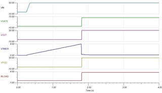
But I am not getting the TIMER waveform same as reference simulation file. Attached simulation files.LM5069 Simulation.zip
Please let me know if there is any error in my circuit..
Regards
Srikanth Kacchu
Hi Srikanth,
I have simulated and it is matching. Can you share your simulation result to look at the issue.
Best Regards,
Rakesh
Hi Rakesh
Please ignore previous attachment and consider this.
Regards
Srikanth Kacchu
Hi,
Because timer cap values and power limit settings are different, you will see different Vtimer profile.
In the original the timer cap is large so it gets charged very slowly.
Please zoom out and check
Best Regards,
Rakesh
Hi Rakesh
But why VTIMER again getting charged after power up discharge in my design which is not observed in the image shared by you?
Regards
Srikanth Kacchu
Hi Srikanth,
In power limit mode of startup, the timer gets charged during the startup.
It is also charging in the image I shared but only to 330mV due to large Ctimer cap. You can check the variation with different Ctimer caps.
Best Regards,
Rakesh
Hi Rakesh
Thanks for the support. I will check by changing TIMER capacitor.
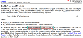
I have one doubt on LM5067. My system input supply is 48V, current rating is 5A and Sense resistor is 10mOhm. How to set the power limit threshold?
How 60W is chosen in the below case in datasheet?
Regards
Srikanth Kacchu
Hi Srikanth,
The power limit value selection depends on the SOA capability of the hot-swap FET. Lower power limit is better to minimize the stress for the FET but it should be good enough to support the load during startup. Because the startup current will be determined by the power limit engine as Plim/vds
Please use design calculator to finalize the components. It is available at www.ti.com/.../LM5067
Best Regards,
Rakesh
Hi Rakesh
I am using LM5067 for 15V power control(Remote ON/OFF control is used). While calculation in TI Design Calculation Templete, I am getting -ve value of RIN. Please correct me where I have mistaken?
Attached calculation sheet.LM5067_Design_Calculator_REV_E(-15V).xlsx
Regards
Srikanth Kacchu
Hi Srikanth,
The formula was given considering standard 48 V and 24V rail applications. Please use below one
Rin = (Vinmin - Vzmax)/2mA = (14.25V - 13.65V)/2mA = 0.3kOhm
Best Regards,
Rakesh
Hi Rakesh
We are using this LM5067/LM5069 just for remote ON/OFF control only. We have seen100uF/100V Electrolytic capacitors are used at the input and output. Is it necessary to use electrolytic or shall we use Ceramic/Tantalum? Also, what is the usual capacitance required for 48V @ 5A (continuous)?
Regards
Srikanth Kacchu
Hi Rakesh
Unfortunately I clicked on Resolved. Please clarify in the same discussion if possible.
Regards
Srikanth Kacchu
Hi Rakesh
I have identified an open collector optocoupler(TLP2362(E)) for remote power ON/OFF at EN pin of LM5067.
As per datasheet recommendation, Emitter to connected to negative system input. But this optocoupler Emitted is connected to internal ground of optocoupler. Does it affects functionality?
Regards
Srikanth Kacchu
Hi Srikanth,
Hot-swap controller does not require large capacitance at the input and the output. You can use as low as 0.1uF just for noise filtering.
You can use TLP2362, connect pin4 to the negative system input.
Best Regards,
Rakesh
Hi Rakesh
How to take care of the in-rush current with 0.1uF decap? We have 5A continuous load on 48V.
Regards
Srikanth Kacchu
Hi Rakesh
Please find the attached design files for my requirement.
Please review and provide observations.
Regards
Srikanth KacchuTI_HotswapControllerReview.zip
Hi Srikanth,
I will review all your 4 designs and get back by end of Wednesday.
Best Regards,
Rakesh
Hi Rakesh
As per your suggestion, we have removed 100uF/100V at the input and output and provided 10uF option along with 1uF.
How these capacitors will control the inrush current?
Did you complete the review?
Regards
Srikanth Kacchu
Hi Srikanth,
Larger capacitance causes inrush currents. So, lower the value, better it is from the inrush current point of view.
All your 4 designs looking good. Few comments..
Why are you using 150V rated FETs on +15V and -15V designs.? I assume, it is to reuse the same components from 48V designs.
To improve SOA margin, you can reduce timer cap on +15V and -15V designs to 100nF. Also, TPS25947 and TPS1663 can be used for 15V and 48V rails. Please have a look and let me know.
Best Regards,
Rakesh
Hi Rakesh
Thanks for the review.
TPS25947 looks to fit for +15V and TPS1663 for +48V. But these devices have internal MOSFET and we decided to use externa MOSFET to be safe from Thermal aspect. Do we have any disadvantages with existing devices?
Also, above parts looks for positive voltages only. What about negative voltages? Shall we use same parts?
Regards
Srikanth Kacchu
Hi Rakesh
I have updated decap at input and output as 10uF along with 1uF. What value should I consider in TI's "LM5069_Desin_Calculation"?
Regards
Srikanth Kacchu
It is mainly due to space efficiency with eFuses
For now we don't have -ve eFuses. Can you let us know your system details, product and what loads are fed from -15V, -48V ?
Hi Rakesh
How to choose Input and Output Protection TVS diode? Datasheet recommends SMBJ30A-13-F is agood choice and EVM has SMBJ70A.
Can I use two different TVS for +/-15V and +/-48V?
Regards
Srikanth Kacchu
Hi Rakesh
Can you please suggest part number of D1(schottky diode) for my requirement when the load is inductive?
Regards
Srikanth Kacchu
Please refer https://e2e.ti.com/blogs_/b/powerhouse/posts/selecting-tvs-diodes-in-hot-swap-and-oring-applications and https://www.powerelectronics.com/technologies/circuit-protection-ics/article/21853356/tvs-clamping-in-hotswap-circuits
You can use SMBJ18A for +15V and -15V designs and SMBJ54A for +48V and -48V designs
Schottky diode:
Use B220a-13-f for 15V designs and B260a-13-f for 48V designs.
BR, Rakesh
Hi Rakesh
Shottky diode has Average Rectified current of 2A only. Does it supports my load current of 5A?
Regards
Srikanth Kacchu
Can you let us know your system details, product and what loads are fed from -15V, -48V ?
Hi Rakesh
+/-48V and +/-15V will drive motor amplifiers as shown in below image. Pls let me know for more details.
Regards
Srikanth Kacchu
Hi Srikanth,
Thanks!
Schottky diode should have "Non-Repetitive Peak Forward Surge Current" rating higher than your system current. Lower average current is fine. Note that, it has freewheel very short internal <10us during turn-off events.
BR, Rakesh