This thread has been locked.

If you have a related question, please click the "Ask a related question" button in the top right corner. The newly created question will be automatically linked to this question.

UC2856-Q1: External pull down of error amp output

Part Number: UC2856-Q1
Other Parts Discussed in Thread: UC3856, UC2856

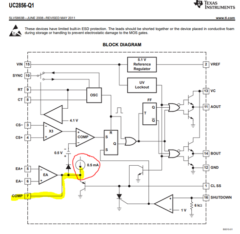
I would like to be able to disable the PWM comparator without discharging the soft start capacitor.  I would like to implement this by pulling the COMP pin low in the same manner as current limit/soft start function is implemented as is shown in the block diagram.  Is this acceptable?  If so, are there any special considerations/caveats  on how the COMP pin is pulled low - like minimum voltage limitations, etc.?  I am planning on using the open collector output of a comparator (without a pull-up resistor) to perform this function.

Thank you very much for your time and help,

Bob Callanan

  • Hi Bob,

    Thanks for connecting through E2E. From the UC2856 block diagram below, you can see the 0.5 mA internal current source connected to COMP? There is no current limiting on this internal current source. COMP does not want to be shorted to GND because we will damage that source and have worse problems to worry about than SS. You have a couple options. UC2856 is a bipolar process PWM but the UCC2808A BiCMOS PWM does not have this internal current source and you can pull COMP to GND as a shutdown method. This IC also does not have some of the other features that may have drawn you to UC3856 such as SS, diff current sense and SYNC. You can view the full parametric list of TI dual output PWM controllers here. If you need to stay with UC2856 and want to shut down without discharging SS, you need to pull CS+ (pin 4) HIGH but also verify shut down and restart behavior to see if this is acceptable. Saturate the CS Amp, force the non-inverting input of the PWM comparator HIGH and command zero duty cycle.

    Regards,

    Steve M

  • Hi Steve:

    Thanks for the response -

    Follow-up question.  Instead of pulling the COMP pin to ground - what if one were to use a PNP emitter follower to pull down the COMP pin in the same manner as the CL SS pin as shown in the UC2856 block diagram?  That would pull the COMP pin not to ground, but to one VBE drop above ground.

    Sincerely,

    Bob Callanan

  • Bob,

    You will have to try and test according to your requirements. The issue is that you can't present such a low impedance that will damage the internal 0.5mA current source. If you increase the impedance high enough such that you protect the current source, you will most likely not pull low enough to disable the controller.

    Regards,

    Steve M

  • HI Steve:

    I'm going to go ahead and pull up the CS input to disable to reset the PWM latch as you suggested.  I noticed that the maximum input voltage for the CS pins is 3V as listed in the Absolute Maximum Ratings table.  However, in the Electrical Characteristics table Current Sense Amplifier Section the maximum differential voltage is listed as 1.1 V.  I am planning to have the CS- pin tied to ground so how high can I drive CS+ pin to insure that the PWM latch is reset. Is it 1.1 V max or 3V maximum?   Side note - my intention with this line of inquiry is to create a separate pulse to pulse peak current limit function using an external comparator. 

    Thanks again for your time and help,

    Sincerely,

    Bob Callanan

  • Bob,

    You can't exceed 3V common mode on either CS input terminal AND the maximum differential mode voltage must be <1.1V. If CS- is GND then CS+ must be <1.1V.

    Regards,

    Steve M

  • Hi Steve:

    Thanks - I do have a follow-up question to this.  Under normal operation, the CS+ pin will be well below 1.1 V.  However, I am planning to have a separate comparator inject a signal on the +CS pin to terminate the pulse.  Does the CS+ pin need to be less 1.1V under this condition?  My concern is that at with a 1.1 V input, the output of the CS amp will be between 2.75V to 3V and that might not be high enough to reliably to trip the PWM comparator under all operating conditions (i.e. error amplifier saturated under transient condition). 

    At this point, it might be more time efficient if we schedule a phone call to discuss in real time what I am trying to achieve. Please let me know if this is possible.  Best way to reach me is via email. 

    Thanks again for your time and help,

    Sincerely,

    Bob Callanan

  • Bob,

    You are proposing to do something unconventional and this is why I recommended to build the circuit and test it according to your proposal. Because the UC2856 offers a differential CS amp it may be that shutdown is not possible as you are envisioning and this is why a dedicated shutdown pin is provided but this action includes soft-start which you mentioned you want to avoid.

    Steve M

  • Hi Steve:

    Thanks for the fast response.

    It's sounding like the UC2856 is not the best choice for this application as described.   Is there some way we can set up a conversation with you or someone else to discuss my requirements in real time? 

    Thanks again for your time and help,

    Sincerely,

    Bob Callanan

  • Bob,

    email me at: s-mappus@ti.com

    Regards,

    Steve M