This thread has been locked.

If you have a related question, please click the "Ask a related question" button in the top right corner. The newly created question will be automatically linked to this question.

UCC28C41: UCC28C41 work with out burst mode

Part Number: UCC28C41
Other Parts Discussed in Thread: TLV431A, TL431

Hi,

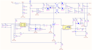
My customer used UCC28C41 to design a flyback with 3.3V/100mA for MUC VCC, they disable the 15V output circuit for the test.

I refer to the spec for voltage mode setup to add 2N222, but now there work in the burst mode in 100mA now.

The L1 is 2mH now, Will increasing the transformer inductance help?

Can UCC28C41 work without burst mode? for MUC need stable voltage to make sure the normal operation.

There are better solutions to give the MUC Vcc power for isolation topology? thanks.

  • Rock,

    UCCx8C4y PWM controllers do not include "burst mode." I believe the customer is seeing "pulse bursts" of packets that look like burst mode but here is the difference: 

    A controller that has true burst mode operation would do something analogous to switching at a minimum duty cycle and then skipping every nth pulse. Some controllers even change to hysteretic mode to achieve pulse skipping. There are different ways to accomplish this but it's done intentionally and in a controlled manner so that the output stays in regulation. Burst mode will also impact output voltage ripple but again, this is done in a controlled and predictable manner.

    When the UCC28C41 COMP voltage falls below the minimum threshold, pulses will stop until the COMP voltage returns. This is uncontrolled and results in erratic output operation. Pulses are randomly and unpredictably missing as opposed to periodically skipping. The behavior can even appear periodic on the scope.

    The converter could have a loop stability issue where COMP is oscillating, especially near the RAMP valley. Please verify that VREF is stable during what is observed as "burst mode" operation? I also notice the TL431 is biased from 3.3V. Be aware that a TL431 is not an op amp that can source current. TL431 can only sink current and since the bias is only 3.3V, I wonder what is the control voltage range seen at the TL431 cathode? You should be using TLV431A (1.24V ref). Also, increasing the mag inductance will force the converter deeper into CCM so be aware of RHPZ in the control loop when operating in CCM. Also, a 1k resistor across the opto diode will assure the TL431 always has at least 1mA bias current regardless of the feedback current through the opto.

    The VCC biasing method looks correct but you should isolate the bootstrap VCC bias capacitors from VCC so they do not need to be charged during initial startup before switching begins. Consider moving C21, C23 to the other side of the the 10 Ω resistor and then also add a second diode after the two capacitors. Coming from the bias winding it should be: diode, 2 parallel caps, diode, 10 Ω resistor...in that order. When you make this change, you will have a better startup/bias solution but then I question if C36=1μF is enough VCC capacitance? C36 may need to increase.

    Regards,

    Steve M