This thread has been locked.

If you have a related question, please click the "Ask a related question" button in the top right corner. The newly created question will be automatically linked to this question.

TPS25982: Parallel TPS25982 24V @ 20A Hot Swap Protection

Part Number: TPS25982

Hello E2E, 

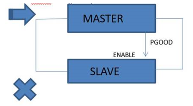
Is it possible / practical to put two TPS25982 eFuses together for a load that could see 20A?  Would the devices be able to share current evenly?  

The other option is a hotswap + external FET, but my customer like integrated eFuses.

Thanks!

Russell

  • Hi Russell,

    Yes it is possible. Do you also need equal load sharing during startup? 

    In steady state, all e-fuses operate in deep triode region, therefore acting as very small resistors. Resistors have a positive temperature coefficient. Therefore, if one of the resistors initially carries more current, its resistance increases, leading to a decrease in its current. Therefore, we have a self-regulating phenomenon at steady state that ensures almost equal load sharing. 

    As the current is equally shared in linear region of a FETs due to their positive temperature coefficient we do not have a problem in steady state for parallel efuses. So, if one TPS25982 can startup into capacitive load and enable the parallel TPS25982 with its PG, then the load current is shared between these devices.

    But we have seen while testing that during overcurrent event due to mismatch in two parallel path there can be unequal current distribution due to which system response is not as expected. So we have following recommendations to overcome this:

    1.  Set Device 1 as master by connecting its PG pin to EN pin of second device(slave device).

    2.Use same ITIMER setting for both devices

    3. Set up both devices for latch-off operation (RETRY_DLY = GND)

    4. Set device #2(slave) ILIM to 50% of total system ILIM and device #1(Master) ILIM to be 10% lower than that of device #2. This ensures that device #1 always detects overcurrent first and takes control of the overall circuit-breaker action. This will ensure that device 1 first turns off after ITIMER which will  cause PGOOD of master to go low and will cause enable of slave to go low and will also turn slave off. So overall your system will see that current through system is going zero after ITIMER .

    5. Use Circuit breaker variant

    Regards

    Kunal Goel

  • Closing thread for now. Let me know if you have further query .

    Regards

    Kunal Goel