This thread has been locked.

If you have a related question, please click the "Ask a related question" button in the top right corner. The newly created question will be automatically linked to this question.

BQ25300: Topology of a charger and a boost converter at the output

Part Number: BQ25300
Other Parts Discussed in Thread: INA181

Hi,

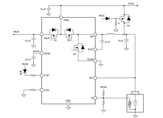
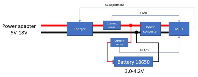
I am designing a single cell charger with the charger IC being the BQ25300 and a boost converter at the output in order to increase the voltage from the battery range 3.0-4.2V to a stable CV 5.0V.

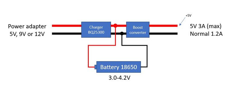
My concern is focused on how BQ25300 will behave when the power adapter is connected while the load at the 5V output of the boost converter is drawing some current.

At 9.3.2 Battery Charging Management i read "The charger terminates the charging cycle when the charging current is below termination threshold ITERM and charge voltage is above recharge threshold(VBATREG - VRECHG_HYS), and device is not in IINDPM or thermal regulation." 

My concern is whether the charger will be able to function properly with the boost converter and the load connected.

The way i understand it (until i don't) is as follows:

Scenario: The boost converter draws 1.5A from the battery with its' voltage (under load) being 3.8V. The charger is connected to the battery and gets into fast charging mode as per ICHG (set by the R). Part of the ICHG goes to the battery and the rest to the boost converter. Since battery is being charged with a current > 0A its' voltage will eventually cross the (VBATREG - VRECHG_HYS) threshold. I am not sure how this scenario goes on given that the boost converter continues to draw 1.5A from the battery. Can you pls fill in the gap?

What i do not understand is how the charging current is set based on the battery voltage level. Can you pls clarify on that?

Regards

Manos Tsachalidis

  • Hi Manos,

        In a non powerpath topology (which BQ25300 is) the total current output from the charger is sensed as charge current. In this case the charge current setting is the max charge current output by the charger IC in CC charging, and from this total output charge current, the load is supplied and the battery is supplied. In this configuration, there will be an issue for the charger to detect termination if the load of the boost converter is always enabled, as charger IC will detect at a minimum the load current, but never satisfy the Iterm condition.

      It would be a more robust design if you were to add a PFET between PMID and battery as shown below, and have your load and boost converter hanging off of the SYS rail shown below:

    If you have only 5V, boost converter has pass through mode - (IR drop across FET), however if you have possibility of 9V, 12V etc, you would need a buck boost circuit at SYS instead of a boost converter. When input is present, load is supplied by input, and when input is absent, then battery can supply load.

  • Thanks Kedar for your message,

    The way i see it is that i am dealing with a case which is rather a bit more complex than just charging a battery.

    The charger input supply rail will most probably be 12 volts since i want to lower the current at that point. I am going to use a pogo pin connector which is susceptible to dust and corrosion so that contact resistance will probably rise with aging.

    There will be a microcontroller after the boost converter which will drive P-channel mosfets in order to drive loads and have buttons for controlling various aspects of the project. So i was thinking implementing manually the following in order get out of this mess or getting myself in a more difficult situation.

    Do you know of any TI chip that offers anything close to what i am looking for?

    Could you suggest a topology including the boost converter?

    Anything that could help me will be highly appreciated.

    The shortage of ICs around the distributors is also a nightmare so i know this will be challenging.

    Awaiting your suggestion.

    Thanks in advance.

    Regards

    Manos Tsachalidis

  • Hi Manos,

       We have buck boost chargers in our portfolio, however they cannot boost from the battery to the SYS rail, which in your case SYS is powering your MCU.

    There are 2 options depending on how much load the boost converter would consume, and what your charge current/termination currents are.

        1. Assuming load to supply boost converter (if it is only powering the MCU the load shouldn't be large?) is < termination current threshold, then there is no issue with termination. If not, then charger would not terminate. Again this would not be a huge issue as the battery would not be fully topped off. At the same time, while adapter is plugged in, the adapter will be providing the load and would not drain the battery too much,

        2. Are you looking for standalone IC only? Using a host controlled IC that has OTG capability will allow you to power the MCU off of the PMID pin. In forward mode with adapter present, you would have adapter voltage - IR drop present on PMID, and when adapter absent, you could go into OTG mode and boost from the battery voltage to PMID. In this situation you would only have a buck IC present at PMID to buck down to MCU required supply. This is more convenient as it would not interfere with termination. It would require I2C communication and be host controlled, which require more software, however it does look like you have an MCU in your system already.

  • Thanks Kedar for your message,

    I had to adopt a boost-buck topology (boost to 5V CV from battery & then buck to 3.3V CV) because there was a need for an intermediate 5V rail.

    The MCU is not the only load. You were correct that if the MCU was the only load the charger would not have a problem charging the battery.

    However, a MT7628 CPU/WiFi board will be connected after the buck. So the current requirement is 1A avg @ 3.3V. The MCU will play a significant role in the charging process since i will use a bidirectional INA181 to measure mAhrs in order to be able to tell when to disable BQ25300 when the battery load (boost, buck & MT7628) is significantly > 0 or even measure the battery voltage to avoid overcharging (however that is already a function of BQ25300). So it seems that, with the current topology i am focusing on, there will be plenty of options to play with.

    Thanks again for your message. I will close this thread. If you see anything of the above (in my last msg) being seriously wrong pls feel free to let me know.

    Regards

    Manos Tsachalidis