Because of the Thanksgiving holiday in the U.S., TI E2E™ design support forum responses may be delayed from November 25 through December 2. Thank you for your patience.

This thread has been locked.

If you have a related question, please click the "Ask a related question" button in the top right corner. The newly created question will be automatically linked to this question.

[FAQ] UCC21750: How can we adjust the DESAT detection threshold in UCC217xx & ISO5x5x?

Part Number: UCC21750
Other Parts Discussed in Thread: UCC21759-Q1, ISO5451-Q1, ISO5851, ISO5452, ISO5851-Q1, UCC21710, ISO5852S-Q1, ISO5451, ISO5452-Q1, ISO5852S, UCC21710-Q1, ISO5852S-EP,

UCC21750/59/10 and ISO5x5x variants offer integrated short-circuit/overcurrent detection and protection with DESAT detection, which internally has a 9V threshold.

How can we adjust this threshold to tailor it for different devices, including both IGBTs and SiC?

Parts with DESAT detection include: UCC21710, UCC21710-Q1, UCC21750, UCC21750-Q1, UCC21759-Q1, ISO5451, ISO5451-Q1, ISO5851, ISO5851-Q1, ISO5452, ISO5452-Q1, ISO5852S, ISO5852S-Q1, ISO5852S-EP, ISO5500

  • Gate drivers with DESAT protection have a built-in threshold which is effective for many IGBTs, but could be slightly too high or too low for other IGBTs or other types of device. This DESAT detection threshold can be tailored to suit different devices simply by changing discrete components in the DESAT circuit.

    This Document is available as in PDF format, link below

    Adjusting the DESAT Threshold.pdf


    ToC

    1. Intro
    2. What is Desaturation in an IGBT?
    3. How does the DESAT detection circuit work?
    4. Why adjust the DESAT threshold?
    5. How do we adjust the DESAT threshold?
    6. References & additional resources

    Intro

    DESAT is a short-circuit/overcurrent detection system integrated in UCC5870, UCC217xx, and ISO5x5x. As its name suggest, DESAT detects "desaturation" of an IGBT and is triggered when VCE rises above a certain threshold set by the design. VCE rising corresponds with the IGBT leaving saturation region and approaching the active region. After DESAT detection, gate drivers (including ISO5x5x and UCC217xx families) will immediately begin pulling the gate low to turn off the IGBT and end the short circuit condition.

    Gate drivers with DESAT protection have a built-in threshold which is effective for many IGBTs, but could be slightly too high or too low for other IGBTs or other types of device. This DESAT detection threshold can be tailored to suit different devices simply by changing discrete components in the DESAT circuit.

    What is Desaturation in an IGBT?

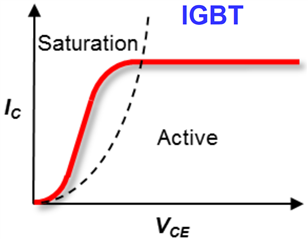
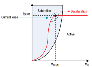
    The optimal operating point of IGBTs in power applications is in the saturation region, where VCE and thus dissipated power are controlled. In the event of a short circuit condition (for example if both high and low-side IGBTs get turned ON simulateously), VCEwill rise quickly while collector current saturates. This puts the IGBT in the active region of operation. A general IC VCE curve is shown in Figure 1.

    Active region is very undesirable for IGBTs in power applications because this causes unsustainably high power dissipation in the bipolar junction and a swift failure of the IGBT itself. This "desaturation" concept is in contrast to FETs, where rising  VGS leads to the device approaching saturation region (rather than leaving it), and where devices are operated in the linear region for power applications. Please see here for additional information on Desaturation.

    In FETs, DESAT detection would therefore be utilized for detecting "saturation" rather than "desaturation," though for SiC FETs in particular direct Over-current can be preferable due to SiC's drain characteristics. The difference in DESAT efficacy between IGBT and SiC is explained further in this eBook.

    Figure 1: IGBT Collector Characteristics

    Figure 1: IGBT Collector Characteristics

    How does the DESAT detection circuit work?

    DESAT system detects when the collector voltage VCis above a threshold, VDESAT, though not directly.

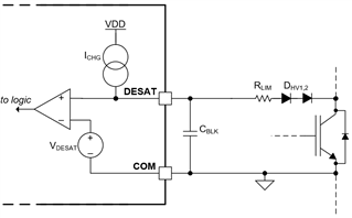
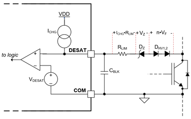
    Figure 2 shows a standard DESAT implementation.

    Figure 2: Typical DESAT circuit

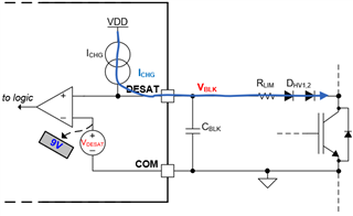
    During normal operation, the IGBT is in saturation, VCis low and and the diodes DHV1,2 are forward biased. The ICHG current can then flow through the diodes to the collector, preventing the blanking capacitor CBLK from charging, as shown in Figure 3.

    Figure 3: DESAT circuit during normal IGBT operation

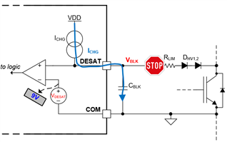
    In short-circuit, VCrises and reverse-biases DHV1,2, so the ICHG current now charges the blanking capacitor CBLK , as shown in Figure 4.

    Figure 4: DESAT during Short-circuit

    After a time (set by the capacitance value), the voltage on the cap exceeds the internal threshold  VDESAT and the comparator indicates that DESAT is detected. The collector voltage where ICHG begins charging the blanking capacitor is VC is considered the system DESAT detection threshold.

     Due to the presence of the DHV1,2, the voltage at the DESAT pin when the current source begins charging the blanking capacitor will be higher than VCE  by 1 or 2 forward voltage drops , or VC+2VF . We must also consider the drop across the series resistor RLIM due to the internal current source. Therefore, we find the effective DESAT threshold, measured at the collector as VCE(DESAT),=VDESAT 2VFICHGRLIM.

    In short, the DESAT threshold is the voltage when the diodes stop conducting, which tells the system VCE is too high.

    Why adjust the DESAT threshold?

    Not all IGBTs are identical, so their VCE / IC transfer characteristics are also different.

    The DESAT detection threshold is usually chosen at the "knee voltage" (often 7-10V), depicted in Figure 5, which is the point at which the collector current saturates and is akin to VDSAT for MOSFETs. Designers may wish to choose the effective DESAT detection threshold to suit an IGBT with a different knee voltage, or possibly choose a threshold below the knee voltage to have earlier DESAT detection.

    Figure 5: IGBT Current Knee

    How do we adjust the DESAT threshold?

    The methods to adjust the DESAT detection threshold involve making changes to the components in series between the DESAT pin and the IGBT collector. These methods are summarized in Table 1

    Changing the number of series HV blocking diodes allows us to decrease the threshold in steps of the diode VF. Similarly, we can increase the detection threshold in larger increments by adding a zener diode, as shown in Figure 6. With this, we find that

    VCE(DESAT),=VDESAT VZnVFICHGRLIM, where n is the number of HV blocking diodes, minimum 1, though often 2 are necessary in order to stand off working voltages of 1kV and up.

    To a lesser extent, small adjustments to the threshold can also be made by changing the value of RLIM, though this should not be used for adjustments larger than a few hundred mV. A zener diode may be used to make larger ( for example, 3V) changes to the DESAT detection threshold and are available in several knee voltages. When selecting a zener, the voltage drop will depend on the current bias–in this case,  ICHG.

    Figure 6

    Change
    Effect on DESAT Threshold
    Add (or remove) HV Blocking diodes

    Decreases threshold by total diode VF

    Add a zener diode

    Decreases threshold  by zener VZ

    Change limiting resistor value

    Decreases threshold by ICHGRLIM

    Table 1: DESAT Threshold Adjustments Summary