This thread has been locked.

If you have a related question, please click the "Ask a related question" button in the top right corner. The newly created question will be automatically linked to this question.

[FAQ] UCC21750: How can we Increase DESAT Charging current for faster Short-circuit detection time in UCC217xx and ISO5x5x?

Other Parts Discussed in Thread: UCC21759-Q1, UCC21750, ISO5451-Q1, ISO5851, ISO5452, ISO5851-Q1, UCC21710, ISO5852S-Q1, ISO5451, ISO5452-Q1, ISO5852S, UCC21710-Q1, ISO5852S-EP, UCC21750-Q1

For SiC driving, we need faster short-circuit detection time!

This value is dictated by the value of the blanking capacitor and the fixed internal DESAT charging current (500uA)

How can I have FAST SC-detection time with DESAT without choosing an unfeasibly small value blanking capacitor, so that I can safely design smart gate drivers with DESAT detection for SiC applications?

Parts with DESAT detection include: UCC21710, UCC21710-Q1, UCC21750, UCC21750-Q1, UCC21759-Q1, ISO5451, ISO5451-Q1, ISO5851, ISO5851-Q1, ISO5452, ISO5452-Q1, ISO5852S, ISO5852S-Q1, ISO5852S-EP, ISO5500

  • Gate drivers with DESAT detection are typically tuned for short-circuit detection with IGBTs. One limitation when designing with DESAT-integrated gate drivers is that it is normally difficult to achieve sufficiently short SC detection so we can shut off the SiC FET before damage occurs (within a few us). This is much shorter than with IGBTs, which typically have 10us short circuit withstand time)

    A key challenge in tailoring DESAT detection for SiC FETs is that blanking capacitor values of >100pF are needed to provide robust protection against false-positives and maintaining a reliable detection.

    The internal charging current that charges the blanking cap (and thus sets blanking time) is fixed in devices with DESAT pins (500uA), so our main method of control of blanking time is typically changing cap value! The nature of high-power applications means there is a potential for transients to couple through the HV blocking diodes in the DESAT circuit and cause FALSE POSITIVE detection, so choosing a very small capacitor is a problem.

    This is a challenge with devices with DESAT pin (UCC21710, UCC21750/59, and ISO5x5x family). Devices which have OC pin can be configured as OC-for-DESAT, sometimes called "pseudo-DESAT" do not share this limitation and is well suited for SiC. OC-DESAT allows designers to arbitrarily set DESAT detection threshold, and td

    However, with a simple modification to the typical circuit, we can also add a second path for Blanking cap charging current to devices with DESAT pin.

    This allows us to have FASTER short-circuit detection that can effectively protect SiC FETs, without choosing a miniscule-valued blanking capacitor, removing the tradeoff between detection time and SC protection circuit reliability.

    Another important aspect of design is tuning DESAT detection threshold (an E2E FAQ) to have earlier detection.


    Intro

    UCC2175x and ISO5x5x detect and protect against short-circuits with integrated DESAT detection. The DESAT system has an internal current source which charges an external capacitor in order to set a "blanking" time to prevent false positives. In some cases, designers may want to increase the charging current to the blanking to decrease the fault-to-shutdown time. This is crucial when driving SiC, since their rated short-circuit withstand time is much shorter than with IGBTs. The blanking capacitor could also be made smaller, but we do not want it too small, as the blanking capacitor helps reject noise on the DESAT pin.

    Similarly to the implementation of OC-as-DESAT with UCC217xx variants with OC pin, we can supplement the internal DESAT current source in UCC2175x and ISO5x5x using external components.

    How does the DESAT detection work?

    For more details on short-circuit detection methods, please see our eBook, IGBT & SiC gate driver fundamentals.

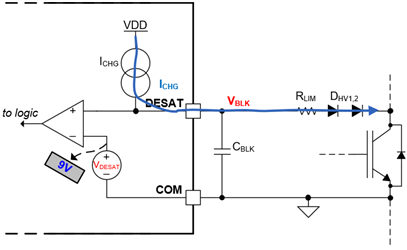
    During normal operation, the internal current source ICHG  flows to the collector through the series resistor and HV blocking diodes, as shown in Figure 1, where VBLK is the voltage across the blanking capacitor CBLK and the voltage at the DESAT pin. This voltage is thus below the internal DESAT detection threshold VDESAT (9V for ISO5x5x and UCC21750/59). 

    Figure 1: DESAT system during normal operation

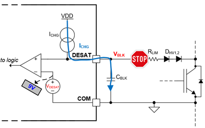
    In an overcurrent/short-circuit event, shown in Figure 2, the collector/drain voltage rise and the HV blocking diodes are reverse biased. The charging current now charges the blanking capacitor, which after a time tBLK, exceeds the internal threshold VDESAT . After a short deglitch-time, a DESAT event is detected and the driver will shutdown the switch to prevent damage. 

    Figure 2: DESAT system during short circuit

    In this standard configuration of , we can estimate tBLK quite simply from our chosen CBLK and the fixed parameters ICHG and VDESAT, as in (1).

    As we can see, the time from fault-to-shutdown depends on the charging current ICHG and the value of the blanking cap CBLK. If we want a faster detection time, we can reduce CBLK to an extent (order of 100pF), but making CBLK too small may increase the rate of false positives and reduce noise immunity, since this capacitor doubles as a filter against transients through the HV diode(s). By instead increasing the charging current, we can have a reasonable CBLK and still have a short tBLK. Internally, this current source is fixed, so we must augment this current using external components.


    How can we increase the DESAT charging current?

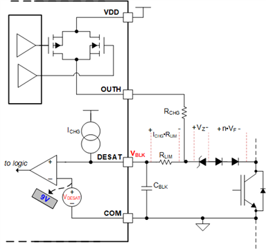
    The simplest way we can increase the charging current is to tack on a resistor, as shown in Figure 3. This resistor's head can be placed either on OUTH/OUT or VDD/VCC2 pins. The benefit of placing on OUTH is that the additional current will only flow during turn-on, which is the only time DESAT detection is active, conserving a little bit of power.

    If the resistor is placed on OUTH, there is a potential for DESAT to go negative during turn-off if negative bias supply is used but due to the value of RCHG, this is a non-issue and the fact that Schottky and Zener are usually placed between the DESAT pin and COM. Optionally, a Schottky diode DCHG can be used which prevents reverse-flow of current during turn-off. If this diode is used, VDD in the following equations should be replaced with (VDDVF) to account for the diode's forward voltage drop, though practically, accounting for this will not change dramatically shift the calculation.

    Because the current delivered from RCHG depends on the value of VBLK, the value at the DESAT pin, its current is not constant and the calculation

    Figure 3: DESAT w/ Auxiliary Resistor Configuration

    We could also implement a constant-current source externally, such as the PNP-based circuit shown in Figure 4, but this increases cost, complexity, and PCB area. Our estimate for tBLK using a constant current source is also simple, since we just need to sum ICHG and ICHG2, shown in (2).

    Figure 4: DESAT w/ External constant-current source

    Calculating tBLK for an Aux. Resistor Configuration

    To avoid the overly verbose "derivation", feel free to skip to the answer.

    From the fundamental capacitor-current relationship, we can set up a simple differential equation as in (3) using the internal current source as well as current across RCHG, which varies in time.


    Rearranging and dividing by CBLK, we have  in (4) which is very typical ODE of the form in (5) with a straightforward solution. 


    The generalized solution of (5) is (6). So we can easily substitute our knowns and find the full expression, where c1 is based on our initial condition. 

    The initial condition would actually depend on the type of short-circuit event. If the IGBT/FET turned on into a short (also called hard switching fault or HSF), the initial condition VBLK(0) would be nearly 0V. If there was instead an overcurrent/overload event during normal IGBT conduction (known as fault-under-load or FUL), there would already be some voltage across CBLK because the ICHG will drop a voltage across the HV diodes and RLIM. The blanking time under an HSF event would, ideally, be longer than under FUL, so we choose to consider the initial condition VBLK(0)=0V. Under this initial condition, (6) becomes (7).

    For those of us who are less inclined to pencil-and-paper, we could also just use Matlab/Octave to find the solution using the script below, which can then be easily modified to evaluate based on chosen circuit parameters, and fixed parameters such as the DESAT threshold.

    Matlab Solution
    clear; clc;
    syms vblk(t) t rchg cblk vdd vdesat ichg tblk rlim;
    ic=vblk(0)==0; %set initial condition across blanking cap
    capcurr=cblk*diff(vblk,t)==(vdd-vblk)/(rchg+rlim)+ichg; %C*dv/dt = I(t)
    pretty(capcurr);
    eq_blk = vdesat==dsolve(capcurr, ic); %Our voltage at desat pin is solved with the initial condition we set.
    blanktime=solve(eq_blk,t);
    pretty(tblk==blanktime);

    Answer: We find our formula for tBLK based on the internal current source and auxiliary resistor now, which is shown in (8)