This thread has been locked.

If you have a related question, please click the "Ask a related question" button in the top right corner. The newly created question will be automatically linked to this question.

TLV62585: Vout-FB capacitor value for TLV62585

Part Number: TLV62585

Dear TI

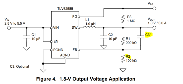
When we measure G-φ margin, it is not enough. So we changed capacitor value that is between Vou-FB from 22pF to 220pF.
Does TLV62585 accept over 22pF?  We would like to use 220pF.

Regards

Kosaka

  • Hi Kosaka,

    Thanks for your question.

    In principle you can change the feedforward capacitor (VOUT-FB cap) value, as long as you check that loop stability, ripple, transient performance, ... are still compatible with your application. Modifying the feedforward capacitor some of these parameters could be no more concordant with the datasheet.

    However 220pF is a value much higher than the one usually recommended from TI.

    What phase margin are you trying to achieve?

    Could you share the test conditions (VIN, VOUT, IOUT) and measurements?

    Which L and C values are you using?

    Thanks,

    Stefano

    All information in this correspondence and in any related correspondence is provided “as is” and “with all faults”, and is subject to TI’s Important Notice (http://www.ti.com/corp/docs/legal/important-notice.shtml).

  • Hi Stefano

    Our Test criteria is Phase margine:45degrees over. Gain margine:10dB over.

    Test condision is Vin=3.3V、Vout=1.1VIout=0A(0%),1.7A(100%)

    We are useing 220pF and 1uH for FB cuitcuit.

    We are using  L:0.24μH   C:22U and 100N for VIN

    Regards,

    Kosaka

  • Hi Kosaka,

    Thanks for the additional info.

    Can you please share the schematic? I am a little confused with what is the 1uH on FB pin.

    Which capacitor is 22uF? CIN or COUT or both?

    In general, you should select an L/COUT configuration inside the LC matrix reported in the device datasheet to assure correct operation.

    As you can see, the recommended inductor is 1uF (not 0.24uH). It is expected that you could have some stability problems with a lower inductor.

    Moreover, the additional compensation introduced by the feedforward capacitor is relates to the product of C3 and R2. Therefore you would obtain a good compensation for C3 = 22pF only if you set R2 = 100kohm.

    Again, this is the recommended configuration from TI.

    Thanks,

    Stefano

    All information in this correspondence and in any related correspondence is provided “as is” and “with all faults”, and is subject to TI’s Important Notice (http://www.ti.com/corp/docs/legal/important-notice.shtml).

  • Hi Stefano

    I atatched our schematics.

    Regards,

    Kosaka

  • Hi Kosaka,

    Thanks for the sharing the schematic.

    Yes, the configuration 1uH + 22uF, should be the optimal one.

    Since the low side resistor is 51k instead of 100k, it is expected that you would need an higher feedforward capacitor to obtain optimal compensation (around 44pF).

    As said before, you could use a different feedforward capacitor, as long as you check that loop stability, ripple, transient performance, ... are still compatible with your application. Modifying the feedforward capacitor some of these parameters could be no more concordant with the datasheet.

    Please ask again if you need further support.

    Thanks,

    Stefano

    All information in this correspondence and in any related correspondence is provided “as is” and “with all faults”, and is subject to TI’s Important Notice (http://www.ti.com/corp/docs/legal/important-notice.shtml).