This thread has been locked.

If you have a related question, please click the "Ask a related question" button in the top right corner. The newly created question will be automatically linked to this question.

LP87565-Q1: unused buck FB

Part Number: LP87565-Q1
Other Parts Discussed in Thread: LP87562-Q1

Hi team,

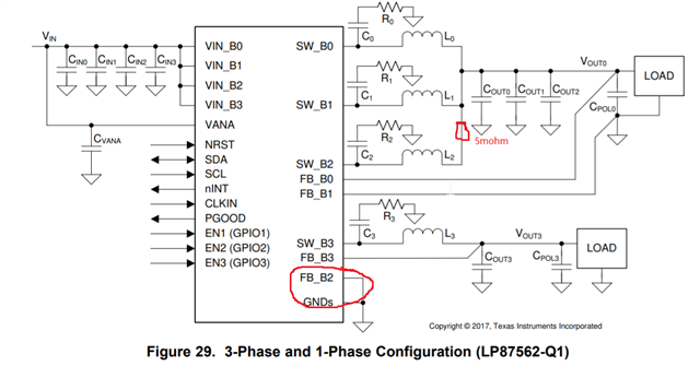
In some case, customer will use 1 phase, for unused channel FB, how to handle? Must connect to GND? Or we can left it float?

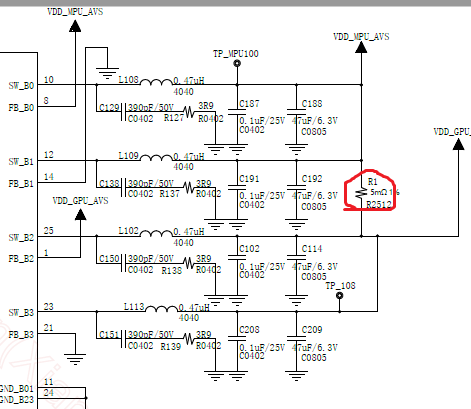
If customer use LP875620, 3ch in 1, since customer want to do hardware compatible design with 87565, the 5mohm resistor is use, will this affect the loop stability?

Thanks

Dongbao

  • Hello Dongbao,

    With LP87565C the PMIC is configured to work in 2+2 phase mode and all bucks must have the external components populated. It is not possible to leave out the output components for one of the bucks. 

    If they want to use PMICs with different phase configurations in same board, they need to place 0ohm shunts to necessary points in buck outputs as well as FB pins to switch from one configuration to another. You can check how it is done in our EVM which uses same board for different phase configurations https://www.ti.com/lit/ug/snvu632/snvu632.pdf. But anyway you cannot short bucks BUCK0+1 to BUCK2+3 as in the diagram if you are using LP87565 since the output voltages are different between BUCK0+1 and BUCK2+3. Also this connection would not work with LP875620, since the FB_B3 is connected to ground. 

    Thanks.

    Regards,

    Tomi Koskela 

  • Hi Tomi,

    Thanks for your quick feedback. Let me put this in this way, for LP87562-Q1:

    1. If i put 5mohm resistor with one of the channel, do you expect it will affect the loop stability?

    2. For FB-B2 connection, can i leave it unconnected?

    Thanks

    Dongbao

  • Hello Dongbao,

    1. It can effect the buck operation at high loads, especially the current balancing. However 5mohm is such a small value that the effect would be very small. It can have effect on loop stability as well and it would be good to place a 0ohm resistor at the FB_B0 to allow phase margin measurement on the board to make sure phase margin is sufficient if this approach is taken. 

    2. FB_B2 should be connected to GND to avoid noise pickup. 

    You can also check the schematic/layout checklist for guidance: https://www.ti.com/lit/zip/snvr480

    Thanks.

    Regards,

    Tomi Koskela