This thread has been locked.

If you have a related question, please click the "Ask a related question" button in the top right corner. The newly created question will be automatically linked to this question.

BQ24616: IC fail and Blow Up

Part Number: BQ24616
The charge controller is failing or blowing up even after showing proper charging operation. 

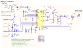
See attached schematic of the charge controller. The system load is directly connected to Vbat.
The downstream load is two buck converters (disabled for all cases) and a 3.3V LDO supply. The external supply is 24V 1.5A. The battery connected is a lithium ion battery with integrated protection circuit: 14.8V 5Ah.
The different boards are labeled by their serial number S##.

Case 1:

On PCB S15, S5, S4. The battery is not completely discharged and connected to the JST. A programmable DC supply is set to 24V 1.5A and enabled after plugged into the charging port. The PG and STAT1 indicate VCC is valid and charging is occurring. No damage here. 

Case 2:

On PCB S15,S5,S4. The battery is completely discharged and connected to the JST. The external supply is hot-plugged. The Charging Chip blows.

Case 3:

On PCB S06. No Battery is connected. The external supply is hot-plugged. PG indicates VCC is valid and the STAT1/STAT2 is off indicating no battery. After a couple of seconds, the charging chip blows.

Case 4:

On PCB S10. The battery is at 14V and connected to the JST. The external supply is hot-plugged. PG indicates VCC is not valid. The external supply is unplugged then plugged back in. PG indicates VCC is valid and STAT1 states it is charging. Then R57 immediately begins to smoke indicating the IC is demanding more current than necessary.

  • Hello,

    Is there any reason you do not have an input current limit?

    Also, you have 60 uF of input capacitance. Our datasheet recommends 10 uF - 20 uF for 3-4A charging current. This will cause 3x-6x the amount of inrush current when hot plugged.

    Any particular reason you do not have the input FETs? They help enable soft start of the input voltage as well as provide reverse blocking protection.

    Thanks,

    Mike Emanuel

    Please click "Resolved' if this answered your question.

  • Hi Michael,

    Since we knew the max current from our external power supply, we did not use the input current limit feature. And since we were not using the input current limit, we did not include the input FETs.

    We initially had 20uF but when our first chip blew, we included an extra 40uF to soften the edge of the voltage hotplug.

  • Hi Mike.
    We designed this to be used in the "Simplified System" configuration, without Power Path or DPM features, as described in the datasheet for the BQ2461X parts, section 10.2.2. The difference in components being that the BQ24616 is JEITA compatible.

    The reason is to reduce the component count and solution cost.  The input diode D5 provides reverse blocking protection. The simple design doesn't provide a soft-start, but there is nothing documented indicating that this is required.

    I believe that that there are other forum entries confirming that the BQ24616 can be used in this mode, but the fact that it is not included in the datasheet does make me question whether there is something unique about this variant.

    We originally designed the circuit with an input capacitance of 20uF (2 X 10uF ceramic), but increased it to reduce the peak voltage seen at the charger chip due to inrush.

  • Hello,

    Please read the application report below about inrush current. Increasing input capacitance comes at the cost of higher inrush current. The report also details several ways to mitigate it. In addition I have attached a report about protecting your power path. Please use the below guidance to protect your input upon hot plug.

    www.ti.com/.../slva670a.pdf

    https://www.ti.com/lit/eb/slyy168/slyy168.pdf

    Thanks,

    Mike Emanuel

    Please click "Resolved" if this answers your question.

  • Mike. Thank. Good info, but I don't see anything specific to the problem at hand. Do you have any specific feedback concerning configuring the BQ24616 without the Power Path and DPM features? 

    I believe that we have provided ample protection against possible over-voltage due to inrush. In fact, the extra caps help protect the chip, at the expense of the external power source, so I don't think that inrush is the issue, unless the BQ24616 can not be used without the DPM input power management.

    Is there any reason to check the lot code? Is it possible we got some bad chips?
    (We will follow up with the PCB Assembler regarding where the chips were sourced, but I'm not sure we'll get a definitive answer.)

    Thanks

  • Hello,

    The only way to diagnose this problem is to probe your board when you hot plug the input. Every failure reported to me stemmed from a hot plug. Please probe the input voltage, the input current, the PH node, and the battery voltage upon hot plug and capture the waveforms.

    Thanks,

    Mike Emanuel

    Please click "Resolved" if this answers your question.