Other Parts Discussed in Thread: TL431, TL1431
I have low current voltage reference applications where my A to K current is less than 7mA. It does not see any added circuit capacitance; >= to 0.01uF.
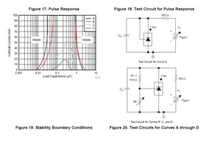
I series two TL1431-EP shorting Ref to K (Test circuit "A") with < 7mA. I have a 10V reference using the TL1431-EP in configuration "C".
Will the TL1431-EP oscillate at cold temperature (-55C) using these application conditions? I have had the older part TL431 oscillate at cold temperatures (-55C) thus my question.
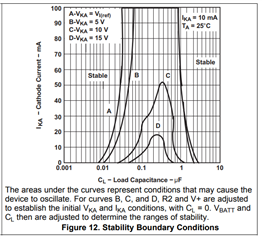
The TL1431-EP Stability Boundaries on the Left have no voltage assigned voltages for the test circuits like in the TL1431 data sheet on the Right.
Is this an improvement in TL1431-EP technology where boundary stability is no longer a function of voltage, configuration, and current or did some one forget to include the voltages as in the TL1431 data sheet?
Pleas advise.
Thanks,
Jim