This thread has been locked.

If you have a related question, please click the "Ask a related question" button in the top right corner. The newly created question will be automatically linked to this question.

TPIC71002-Q1: SPI Parity Mode

Part Number: TPIC71002-Q1

Hi,

I have a few questions about the SPI Parity Mode transfer configuration and behavior for TPIC71002-Q1. We're using 2-frame or 4-frame SPI Burst Transfers.

  1. Datasheet says that "Device supports parity check during Address Mode Transfer." (page 24), but on the next page it says that parity detection results in actions (like setting parity error flag) which "are performed either if the parity failure is detected in the Address Phase or the Data Phase"
    1. While testing it seems that parity checks are done on both address and data phase, but I want to confirm this with you. Are parity checks done during both address and data phase of transfer?
  2. "The device responds with forced parity error during Data Stage (next SPI transfer)."
    1. What exactly is meant by forced parity error? Is it some data sent with wrong parity bit set on purpose, or what is it?
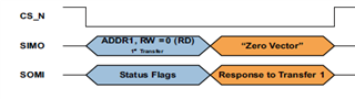
    2. If I enabled parity mode and am using 18-bit SPI transfers ( [8-b address + 1-b address parity] [8-b data + 1-b data parity] ) like the example below, and parity error happens during ADDR1 phase, when should this forced parity error be received by the master? Should it be right after ADDR1 phase in "Response to Transfer 1" or in the next transfer?                         
  3. In which Inhibition Mode should the device be when enabling parity mode?
    1. When device is in IM1, first SPI transfer after enabling parity mode results in data with wrong parity bit being returned during address phase ("1101 0000 x", where x is parity bit and is opposite to correct value regardless of if parity mode configured is even or odd). Is this ok? This doesn't seem to happen on the first SPI transfer after enabling parity mode while device is in IM0.
  4. Why does SPI_ERR flag get set and is read during Device Status phase if previous SPI transfer was Read with Zero Vector being sent after the Address Phase (see screenshot above)? I spoke to a colleague of mine who already contacted you about this issue and he got the answer that this error can be ignored, but can this somehow be remedied so that this doesn't happen?

Best regards,
Tomislav

  • Hi,

    Thank you for your interest in TPIC71002. Let us review your post and feedback to you by July 15th.

    regards

    Shinya 

  • Hi,

    Thank you for your interest in TPIC71002-Q1. Let me response the feedback as follows.

    1. Parity checks are available on both address and data phase.

    2a.Forced parity error means next SPI transfer(data from TPIC71002 to MCU) has an additional parity bit.

    2b.Datasheet does not mention about it however I expect that parity error happens right after ADDR1 phase.

    3.Please enable parity mode in IM1 which is mode for device configuration /set up.

    4.Not sure how your colleague got above information from someone in TI. Acc to datasheet SPI_ERR is set if error is detected such as Number of SPI Clock cycles in the SPI Frame (between CS_N driven low and CS_N driven high) is not 8 (for single SPI Transfers), or multiple of 8 (for SPI Burst Transfers).

    regards

    Shinya

  • Hi Shinya,

    Thanks for the answers, but there are still some things that are not clear to me.

    2a. What is then the point of a Forced parity error? If parity mode is enabled, an additional parity bit will be sent by the TPIC either way (both if parity error happened during the last transfer and if it didn't). How should these 2 cases be distinguished from one another during this transfer (data from TPIC71002 to MCU)? I know SPI_ERR/PERR flags will be set if parity error occurred, but then another transfer needs to be made after this one just to get the Status Flags and/or read the PAR register.

    4. That's what is written in the datasheet, but I checked the signals using an oscilloscope and the number of SCK cycles is correct. Here's a recording of an SPI burst transfer with parity mode disabled:

    SCK was recorded on CH1 (yellow) and CS_N is on CH2 (blue). As you can see, there are a total of 16 SCK cycles between CS_N driven low and CS_N driven high. But the problem is that the SPI_ERR flag gets set after every Read Acess. So, if previous SPI transfer was reading data from a register, SPI_ERR flag will be set when status flags are returned during the Address Phase of the next transfer, but if previous transfer was writing to a register, SPI_ERR flag will not be set.

    Also, there's one more thing regarding parity mode. When I was testing writing to a register with parity mode enabled, I tried sending data with wrong parity bits set on purpose. According to the datasheet, if TPIC71002 detects wrong parity in either Address or Data Phase of a Write Access, the write should be ignored and parity error flags set.

    "The Parity Error Flag in the Parity Status register is set. The SPI Write Access is ignored regardless if parity error occurred during WR Address Stage or WR Data Stage. If error occurred during WR Address Stage, device forces parity error for Address Stage response in the next SPI transfer. SPI_ERR bit is set in the Status Flag register and returned during next Status Flag response."

    But this does not happen, the value gets written to the register as if no parity error happened. I verified this by reading the value stored in the register before and after the write in which parity error was injected on purpose. I tried setting the wrong parity bit on both Address and Data Stages separately, and then on both Stages at the same time, but the result was the same. Error flags get set, but the value is written when it shouldn't be.

    Best regards,
    Tomislav

  • Hi,

    Thank you for your question. Let me response to you in early of next week.

    regards

    Shinya

  • Hi,

    just bumping the thread so that you don't forget about it  :)

  • Hi,

    Sorry for my late reply.

    2a. I see your point. However based on Datasheet descriptions, I think that forced parity error means next SPI transfer(data from TPIC71002 to MCU) has an additional parity bit.

    4. >>but if previous transfer was writing to a register, SPI_ERR flag will not be set.

       I think TPIC71002 SPI_ERR could have limitation to detect and provide feedback. In order to read SPI_ERR Flag, 9 clk is required. Therefore writing with 8clk may not wok as you mentioned.

    Since I do not have environment to try parity error communication, let me try to response based on datasheet. TPIC71002 may have limitation therefor customer can use with Parity disable mode


    I would like to ask one thing. Is it possible to create new post for further questions? It is helpful and our engineer will be assigned based on your further question.

    Thanks,

    regards

    Shinya 

  • I would like to ask one thing. Is it possible to create new post for further questions? It is helpful and our engineer will be assigned based on your further question.

    Yes, it is. I will create a new post and write all remaining SPI transfer questions I have.

    Best regards,

    Tomislav

  • HI Tomislav,

    Thank you for your reply. Appreciated.

    regards

    Shinya