This thread has been locked.

If you have a related question, please click the "Ask a related question" button in the top right corner. The newly created question will be automatically linked to this question.

TPS7B7702-Q1: reference design for selectable current limit

Part Number: TPS7B7702-Q1

Hi team,

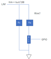
I would like to change Rlim value by MCU depends on the antennas connected to the output.

Could you advise the reference design to achieve this?

Does this configuration below work?

  • Hi Shinji,

    This design concept will work.  The BJT solution will be limited in turn on / turn off time based on the transition frequency.  MOSFET's will not typically have this limitation.  You may wish to consider using MOSFET's instead of BJT's if the turn on / turn off requirements are very fast in your system.  The following MOSFET from TI is incredibly small and fast - you may wish to consider this for your design.

    https://www.ti.com/lit/ds/symlink/csd15380f3.pdf

    Thanks,

    - Stephen

  • Hi Stephen,

    Thank you for your reply. 

    Since I need Q100 device, csdxxx cannot be used. 

    Does the analog switch below also work?

    https://www.ti.com/product/SN74LVC1G3157-Q1

    https://www.ti.com/product/TMUX1309-Q1

    I have a question about the Rlim calculation above. 

    LIM pin is constant current output and the voltage will not be clamped even at 1.233V current limit voltage, correct?

    If I use BJT on bottom and also add Rc(resistor) in parallel to Ra+BJT to make sure LIM pin will not float, 

    then How should I calculate Rlim from given Ra, BJT and Rc?

    (Ra+Rdson(BJT))//Rc?

    regards,

  • Hi Shinji,

    I am reviewing your question and will reply back within 2 business days.

    Thanks,

    - Stephen

  • Hi Shinji,

    Unfortunately I am unfamiliar with those devices from TI, so you will want to submit an E2E request to the product lines which own those devices for support.

    The LIM pin is rated to 7V.  From the block diagram of the LDO, the LIM pin is compared with 1.233V.  This is the voltage on the LIM pin that the regulator tries to maintain for regulation.  There should not be any damage with 1.233V on this pin.

    For the Rlim calculation, you set Rc to be Rlim in the datasheet section 8.2.2.4, and solve for your desired current limit.  This will be the low value of current limit.  Then for the high value of current limit, you must consider the resistance across the switch (Rce for a BJT, Rds for a MOSFET) and add that to Ra.  Then just like you have suggested, it is a parallel resistance calculation.  Rlim = (Ra+Rdson(BJT))//Rc.

    Thanks,

    - Stephen