This thread has been locked.

If you have a related question, please click the "Ask a related question" button in the top right corner. The newly created question will be automatically linked to this question.

TPIC71002-Q1: Design questions (power supply config)

Part Number: TPIC71002-Q1

Dear TI Team,

Can you please answer the below questions regarding the squib driver? A customer would like the power supply config cleared up.

Many thanks,

Daniel

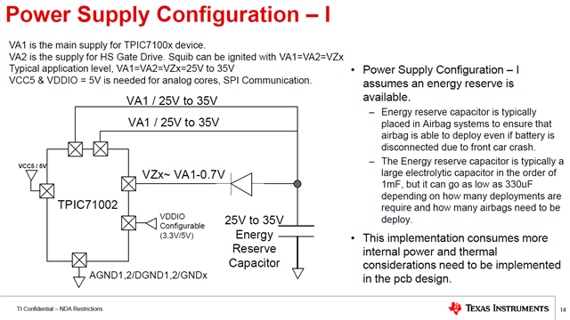
  1. What is the purpose of diode?

Can we connect VAx and VZx together without diode?


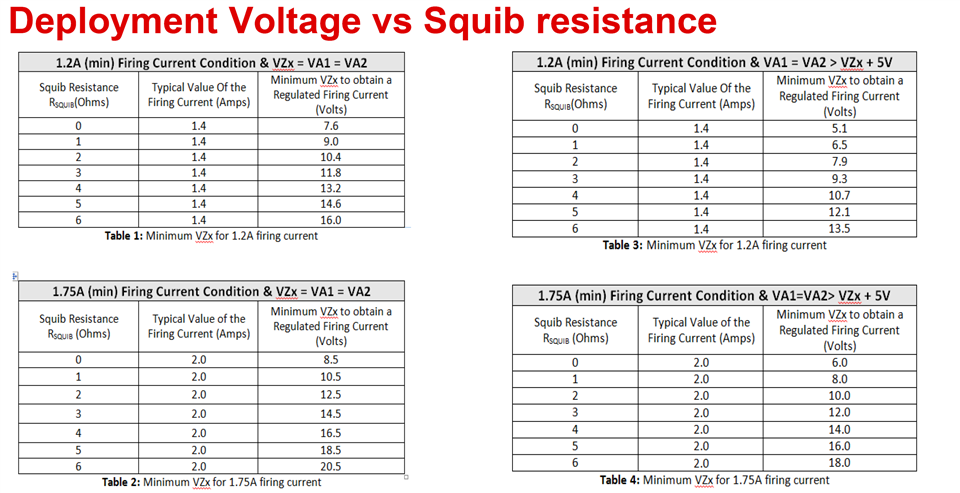
  1. What is the minimum VA/VZ voltage if we use just one pyro element with 2R resistance?

Can we use 18V instead 25V-35V?


  1. What is the minimum capacitance of the energy reserve capacitor?

If we use only one pyro element (2R) is it ok to have 220uF capacitor?

  • Dear Team,

    I would appreciate your support here.

    Many thanks,

    Daniel

  • Daniel, 

    Please find the response for the power supply configuration.

    1. The diode is optional between VA1/2 and VZx. Diode between VA2/VA1 and VZx was recommended for thermal reasons. Our device can support 1.2A, 2ms activation time at 35V.  With the diode in place, we will have about 0.5V to 0.7V drop  from VA1/2 such that the over all Vds drop across the HS_FET can be slightly lowered to provide extra margin from a thermal perspective (i.e. junction temperature rise in the HS_FET during deployment).

    2. Here is the recommended VA1/2 and VZx levels for deployment current and pyro resistance.

    For 1.2A setting , 4 ohms pyro resistance ( i.e. 2x the typical pyro resistance of  2 ohms), min required voltage when VA1=VA2=VZx would be around 14V. So 18V should be fine in this scenario.

    For 1.75A setting,  4 ohms pyro resistance ( i.e. 2x the typical pyro resistance of  2 ohms), min required voltage when VA1=VA2=VZx would be around 16.5V. So 18V should still work be ok.

    3. The minimum required Energy reserve capacitor would be dependent on the max. current specified, activation time and the allowed droop in the VZx level. This capacitor is sized based on the worst case conditions. For instance if the VZx level is allowed to droop from 18V to 17V during deployment ( deltaV of 1V) for  max current of  2.4A  in the 1.75A setting  and 500us deployment time, then

    C= I dt/dV= 2.4A * 0.5m/1= 1.2mF.

    Similar calculation has to be done for 1.2A, 2ms setting.

  • Hi Navaneeth,

    Many thanks for your support! This answered my customer's questions for the time being,

    Kind regards,

    Daniel