This thread has been locked.

If you have a related question, please click the "Ask a related question" button in the top right corner. The newly created question will be automatically linked to this question.

BQ25792: Trickle charge won't go above ~2V

Part Number: BQ25792
Other Parts Discussed in Thread: BQ28Z610,

I have exactly the same problem as this other thread which is now locked. Was this problem ever solved?

https://e2e.ti.com/support/power-management-group/power-management/f/power-management-forum/998618/bq25792-charger-in-trickle-charge?tisearch=e2e-sitesearch&keymatch=bq25792%20trickle#

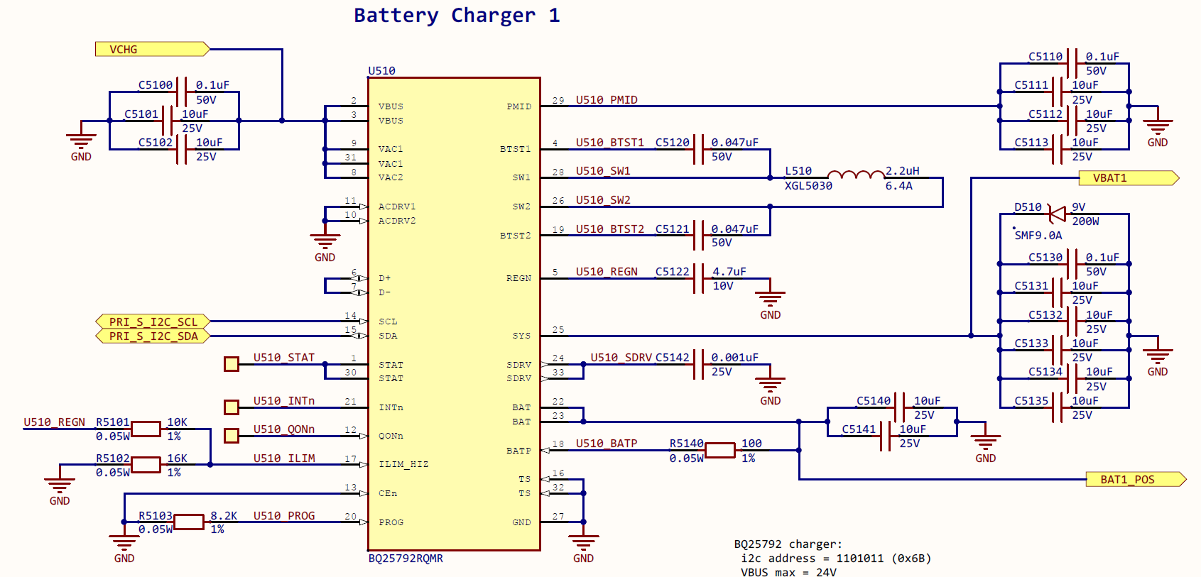
One board shows the problem so far, others work fine. Battery pack has bq28z610 and can be turned on by power supply or another good board of mine. But on the bad board, the BQ25792 won't deliver any current to the pack to raise the voltage above 2V. Charger stuck in trickle charge mode, no faults, no current to battery (measured between charger and battery). Otherwise, this charger works fine when the battery voltage is normal.

I can wake a sleeping battery with a 1K resistor to 6V. But when connected to the charger and touching the 1K, the voltage is clamped at 2V and the battery won't wake. Changing to 100 ohms, the external supply is able to wake the battery even when the charger is connected.

Register dump when not working:

VSYSMIN   00:  7000     VINDPM    05:  3600     PCHG      08:01
VREG      01:  8400     IINDPM    06:  3300     TERM      09:05
ICHG      03:  4200     VOTG      0B:  2800     RCHG      0A:63
                        IOTG      0D:03         TIMR      0E:3D
ChgCtl 0  0F:82         ChgSts 0  1B:0F         TEMP      16:C0
       1  10:00                1  1C:10         NTC0      17:7A
       2  11:00                2  1D:00         NTC1      18:00
       3  12:00                3  1E:10         ICO       19:01
       4  13:29                4  1F:11                          
       5  14:1C                                                    
FltSts 0  20:00         FltFlg 0  26:00         FltMsk 0  2C:00
       1  21:00                1  27:00                1  2D:00
ChgFlg 0  22:00         ChgMsk 0  28:00                          
       1  23:00                1  29:00         AdcCtl    2E:B8
       2  24:00                2  2A:00         AdcDis    2F:00
       3  25:00                3  2B:00         AdcDis    30:00
IBUS      31:    16     IBAT      33:     0     TS        3F:     0
VBUS      35: 11964     VBAT      3B:   112     TDIE      41:    41
VAC1      37: 11912     VSYS      3D:  7347     D+        43:     0
VAC2      39: 11897                             D-        45:     0
DPDM      47:00         Part      48:08           0 err

And from identical circuit on a good board:

VSYSMIN   00:  7000     VINDPM    05:  4800     PCHG      08:01
VREG      01:  8400     IINDPM    06:  3300     TERM      09:05
ICHG      03:  4200     VOTG      0B:  2800     RCHG      0A:63
                        IOTG      0D:03         TIMR      0E:3D
ChgCtl 0  0F:A2         ChgSts 0  1B:0F         TEMP      16:C0
       1  10:00                1  1C:70         NTC0      17:7A
       2  11:00                2  1D:01         NTC1      18:01
       3  12:00                3  1E:00         ICO       19:01
       4  13:29                4  1F:00                          
       5  14:1C                                                    
FltSts 0  20:00         FltFlg 0  26:00         FltMsk 0  2C:00
       1  21:00                1  27:00                1  2D:00
ChgFlg 0  22:00         ChgMsk 0  28:00                          
       1  23:00                1  29:00         AdcCtl    2E:B8
       2  24:00                2  2A:00         AdcDis    2F:00
       3  25:00                3  2B:00         AdcDis    30:00
IBUS      31:  2720     IBAT      33:  4245     TS        3F:     0
VBUS      35: 12063     VBAT      3B:  7310     TDIE      41:    85
VAC1      37: 12019     VSYS      3D:  7367     D+        43:    90
VAC2      39: 12021                             D-        45:   116
DPDM      47:00         Part      48:08           0 err

Before enabling charge to wake the battery, both good and bad chargers show the same register data:

VSYSMIN   00:  7000     VINDPM    05: 11200     PCHG      08:01
VREG      01:  8400     IINDPM    06:  3300     TERM      09:05
ICHG      03:  4200     VOTG      0B:  2800     RCHG      0A:63
                        IOTG      0D:03         TIMR      0E:3D
ChgCtl 0  0F:82         ChgSts 0  1B:0F         TEMP      16:C0
       1  10:00                1  1C:07         NTC0      17:7A
       2  11:00                2  1D:00         NTC1      18:00
       3  12:00                3  1E:10         ICO       19:01
       4  13:29                4  1F:11                          
       5  14:1C                                                    
FltSts 0  20:00         FltFlg 0  26:00         FltMsk 0  2C:00
       1  21:00                1  27:00                1  2D:00
ChgFlg 0  22:00         ChgMsk 0  28:00                          
       1  23:00                1  29:00         AdcCtl    2E:B8
       2  24:00                2  2A:00         AdcDis    2F:00
       3  25:00                3  2B:00         AdcDis    30:00
IBUS      31:     3     IBAT      33:     0     TS        3F:     0
VBUS      35: 12484     VBAT      3B:   110     TDIE      41:    36
VAC1      37: 12460     VSYS      3D:  7315     D+        43:     0
VAC2      39: 12454                             D-        45:     0
DPDM      47:00         Part      48:08           0 err

  • Hi Jim,

    Unfortunately no.  Can you reply with the top IC marking of the good and bad units?  If you increase the capacitance on BAT pin, does that help?  If you change the cell count register to 1S or 3S, does that change anything?  Can you using a current probe to measure the trickle current for the good and bad unit. Please note that changing to 1S with a battery that is charged above 4.2V will result in BATOVP and that changing to 3S will result in potential overvoltage unless you quickly change back to 2S.

    Regards,

    Jeff

  • All parts tested are the same marking: 0AANLZ8. I have two identical charger circuits on each board, so good and bad were assembled at the same time. On the other boards I've tested, both are good.

    I used a diff probe across an inline resistor to check current, but it is zero until the battery turns on (good charger only). The battery is a high impedance before turning on, so the only current is charging a tiny capacitance.

    For the following scope shots, yellow is BAT and magenta is current (100mA/div).

    1) Bad charger at enable. It's suspicious that voltage rises to about VBAT_SHORTZ, then drops to about VBAT_SHORT, then turns on again.

    2) Good charger at enable. The slope to 2.5V is exactly the same as the bad charger, then decreases slightly on the way up to battery turn-on.

    3) Changing CELL count register changes the on/off behavior, but it stays at 2V. Traces top to bottom are 1s, 2s, 3s.

    4) I added 100uF to BAT on both good and bad. That changed the slope but not the behavior.

    Bad:

    5) Good:

  • Hi Jim,

    Thanks. The plots with current didn't come through. You should see 100mA of current from BAT.  Do you have room to place a small decoupling capacitor (0.1uF) from BAT pin to GND, even if you have to scrape off solder mask?  If so, can you retest?  I have finally found an IC in house that has this issue and will be testing it as well.  Thanks again for helping debug!

    Regards,

    Jeff

  • The 0.1uF cap didn't make a difference.

  • Hi Jim,

    Can you try disabling PFM mode and see it that changes anything?  It seems to fix my board.

    Regards,

    Jeff

  • I set reg 0x12 to 0x10, but it didn't help.

    VSYSMIN   00:  7000     VINDPM    05: 11300     PCHG      08:04
    VREG      01:  8400     IINDPM    06:  3300     TERM      09:05
    ICHG      03:  4200     VOTG      0B:  2800     RCHG      0A:63
                            IOTG      0D:03         TIMR      0E:3D
    ChgCtl 0  0F:A2         ChgSts 0  1B:0F         TEMP      16:C0
           1  10:00                1  1C:27         NTC0      17:7A
           2  11:00                2  1D:00         NTC1      18:01
           3  12:30                3  1E:10         ICO       19:01
           4  13:29                4  1F:10
           5  14:1C
    FltSts 0  20:00         FltFlg 0  26:00         FltMsk 0  2C:00
           1  21:00                1  27:00                1  2D:00
    ChgFlg 0  22:00         ChgMsk 0  28:00
           1  23:00                1  29:00         AdcCtl    2E:B8
           2  24:00                2  2A:00         AdcDis    2F:00
           3  25:00                3  2B:00         AdcDis    30:00
    IBUS      31:    49     IBAT      33:     0     TS        3F:     6
    VBUS      35: 12303     VBAT      3B:  2154     TDIE      41:    56
    VAC1      37: 12273     VSYS      3D:  6831     D+        43:    27
    VAC2      39: 12280                             D-        45:    27
    DPDM      47:00         Part      48:08           0 err

  • Hi Jim,

    That is strange.  It fixed my board every time.  I have design looped in on this.  Hopefully, we will have a solution soon.  I will keep you posted.

    Regards,

    Jeff

  • The waveform is different with PFM disabled.

  • Thanks.  What happens if PFM disabled and 1S or 3S or 4S?

  • 1s while PFM is disabled broke it loose - it's charging now.

  • So that's an easy workaround, but I'd like to know there's a good explanation and that it should be dependable. I can always add an external wake-up-the-battery circuit, but of course I don't want to do that.

  • Jim,

    Thanks for testing.  I am waiting on design for a root cause.  But I can explain one thing.  With V(BAT)<VBAT_SHORT~=2.2V, the charger uses a current source to provide ~100mA.  At V(BAT)=2.2V, the charger changes over to a voltage regulating circuit with output voltage set by the cells bits.  CELLS=1S is supposed to regulate to slightly less than 3V while CELLS=2S sets the regulation to slightly more than 4V. 3S and 4S are higher.  I am waiting on design to explain the relationship to PFM.

    Regards,

    Jeff

  • I should further explain that this voltage regulation only last a few hundred ms and then precharge starts.

    Regards,

    Jeff

  • Thanks, Jeff. I look forward to more details! I coded a workaround that sets 1S and no PFM until the battery gas gauge responds on i2c and then switches back to 2S and PFM enabled. That works reliably so far. It should be OK for us as the lower VSYS during that time is still enough to power the microcontroller that controls the charger, and this process only occurs when a new unit is first powered after shipping with batteries shut down.