Hi, the schematic is as below:
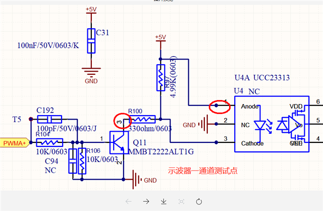
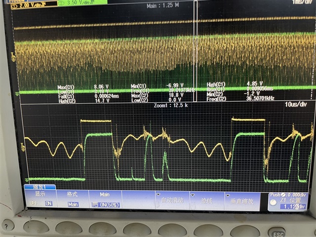
The waveform we measured is as below: yellow- (pin1 of U4 with respect to pin3 of Q11), green- pin 5 of U4.
We can see that there are some ripple on the primary side voltage of UCC23313, and it couples to the secondary side of UCC23313 and make it false turn on.
We have measured pin1 of Q11 and is sure that the input PWM signal is clean.
So we wonder why there will be ripple on voltage pin1-pin3 of U4. It looks like there is oscillation when the transistor Q11 turns off.