This thread has been locked.

If you have a related question, please click the "Ask a related question" button in the top right corner. The newly created question will be automatically linked to this question.

BQ79600-Q1: Safety Mechanism 132 (SM132) - SPI FIFO Register Diagnostic

Part Number: BQ79600-Q1
Other Parts Discussed in Thread: BQ79616-Q1, BQ79616

Hi everyone,

I am implementing an application based on BQ79616-Q1 as stack devices and BQ79600-Q1 as bridge device.

In the BQ79600 safety manual  are described all the safety mechanism (SM) and the assumptions of use (AoU).

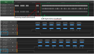
In particular, SM132 is about the SPI FIFO Register diagnostic.

The description says to write some data (32 bytes) into the RX buffer and check the TX buff later in the procedure but I don't understand how to do these steps.

Could someone help me, please?

BR

Diego

  • Hi Diego,

    I do understand your confusion as the FIFO Register Diagnostic test holds a level of disclarity as it appears in the Safety Manual. I have outsourced your query to our systems team and will be sure to treat your request with the upmost urgency. Please expect a response soon.

    Best Regards,

    Christian

  • Hi Christian,

    ok thanks, I look forward for further responses.

    If it can be useful, I am using Safety manual version SLUA984A – JUNE 2020 – REVISED JANUARY 2021. It seems the last version to me, could you confirm it?

    Thanks, BR

    Diego

  • I have similar problem also with SM200, I have some difficulties to understand what should be done in the described procedure.

    • Step 1 of Figure 5-4: "Write SNIF_DET_EN=1 and SNIF_DET_DIS = 0 in DIAG_CTRL Register"
      • I assume it is talking about register in BQ79600 dev, right? If yes, those bits are in register DEV_CONF1 (0x2001) and not DIAG_CTRL. I am using datasheet SLUSDS1A – NOVEMBER 2019 – REVISED AUGUST 2020 as referenece for registers.
    • Step 2: "Write Command to set incorrect CRC fault on top of stack device"
      • I assume that it is done by executing a single device write of bit FLIP_TR_CRC in DIAG_COMM_CTRL (0x336) of BQ79616 top stack device. Is it right?
    • Step 3: "Verify ToneTX is enabled on stack devices"
      • I assume that it is done by executing a stack read of bit FTONE_EN in DEV_CONF (0x002) of BQ79616 devices. Is it right?
      • Doing this stack read doesn't trigger the wrong CRC transmission set in step 2?
    • Step 5: "Wait For top of stack device to send fault tones on COML [DIR_SEL = 0]"
      • What does it mean? How much time I have to wait? Or which signal/register have I to monitor to do this?
      • What about the case that devices are in ring configuration and they are working in reverse mode? Does it change something?

    Thanks for your help.

    BR

    Diego

  • Hi Diego,


    Thank you for your cooperation. Yes, the Safety Manual SLUA984A with January 2021 revision is our latest version. However, we have discovered some edits since then that will be applied to future revisions. Regarding SM132, an additional step is needed (step 7 below) in order to read back the correct data from TX_FIFO.


    • SM132: FIFO Register Diagnostic

    Assumption: RX_FIFO is empty

    1. Host shall write the unlock code 0x0A to SPI_FIFO_UNLOCK
    2. Host shall write [SPI_FIFO_DIAG_GO] = 1 to start the FIFO diagnostics. (SPI_RDY will go low with GO bit and go high again in ~2.5 us)
    3. Wait 100us for command processor and test_ctrl to process GO bit.
    4. The host then writes 32 bytes into RX buffer. (SPI_RDY remains high until RX FIFO is full.)
    5. The ASIC shall copy the RX FIFO to TX FIFOs (SPI_RDY remains low until RX FIFO to TX FIFO copy is complete).
    6. Note : The ASIC copies the contents of RXFIFO 8 times (32 bytes each). First 32 bytes are copied as is, and then each byte of data is rotated left by 1 bit for the second copy. Next, each byte of data is rotated left by 2 bits for the third copy and so on… The final copy of the RXFIFO contents will have each byte rotated by 7 bits.
    7. The host shall wait 40us, check if SPI_RDY =1. If so, that means RX FIFO to TX FIFO is compelte; if not, wait another 40us and re-check.
    8. Host drops nCS, sends a single device read command on MOSI pin (sample: 0x080 0x00 0x2001 0x00 0x2584), ignores data on MISO, raises nCS and waits 5us.
    9. Host drops nCS, reads 128 bytes, raises nCS and waits 5us.
    10. Then host drops nCS, reads another 128 bytes and raises nCS.
    11. Host shall verify the TX FIFO data is as expected.
    12. Host shall send COMM Clear to exit the FIFO DIAG mode.

    This is a logic analyzer capture for your perusal. In the second capture, the zoomed in SPI_RDY behavior is a response to the dummy read command being transmitted. In the third capture, the zoomed image shows the nCS behavior during the dummy read command.

    • SM200: Snif Detector Diagnostic
    1. Your registers are correct (DEV_CONF1- 0x2001) when writing SNIF_DET_EN=1 and SNIF_DET_DIS=0.
    2. In order for the stacked BQ79616 to register a fault, FRIP_TR_CRC will not suffice as it solely changes the CRC bytes in the response frame. Therefore, you will need to change the CRC registers to an incorrect value using the CUST_CRC_HI/ LO (Reg: 0x0036/7) to mismatch that in CUST_CRC_RSLT_LO (Reg: 0x050C/D).
    3. You will then enable FTONE_EN in order to proceed with the diagnostic.
    4. The period between fault tones is 50ms; however, the safety manual suggests waiting for 100ms.
    5. NFAULT will assert when the device detects a full valid tone and therefore, should be monitored on the BQ79600 device.
    6. The BQ79600 sniff detector requires ring communication architecture for this diagnostic to work. Therefore, you do not need to change the procedure if you change the communication direction.

    Thank you Diego and I hope that this information helps.

    Best Regards,

    Christian