This thread has been locked.

If you have a related question, please click the "Ask a related question" button in the top right corner. The newly created question will be automatically linked to this question.

BQ76PL455A-Q1: power supply circuit of BMS Main

Part Number: BQ76PL455A-Q1
Other Parts Discussed in Thread: TMS5701224

Good afternoon
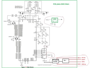
a question about the 5V power supply circuit for powering the BMC Mine board.
1. Figure 1. Do I understand correctly that I need to install a voltage regulator that will supply 5V BQ76PL455A-Q1 from the HV battery and the tms5701224 controller and the controller will transmit information to the system via CAN?


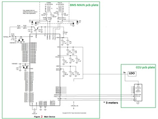
2. Figure 2. The circuit in this figure will not work. Right?

thanks for the answer

  • Hello Oleg,

    The VIO rail is an internal regulator that outputs 5V for the device communications. VIO can be supplied by VP/VDIG. You don't need an external LDO device for the BQ76PL455A-Q1 device (however you can optionally use one).

    3-V to 5-V power input for IO supply. Connect this pin to the same power supply used to drive the source/receiver for the GPIO, FAULT_N, RX, and TX pins. Typically, connect this pin to VP/VDIG for all devices except the base device in the stack. In the base (or single) device, this pin is typically driven from the same supply as the microcontroller I/O pins.

    If VP/VDIG is connected as the power source, this pin should be decoupled with a 0.1-μF capacitor to the digital ground plane. Place a 1-Ω resistor in series from VP to VIO. Locate the decoupling capacitor as close to the VIO pin as possible.

    If another supply is used, decouple with parallel 10-μF and 0.1-μF capacitors

    EDITED

  • yes, I was in a hurry about the regulator. 
    but otherwise am I right?

  • Oleg,

    You should use VIO to power the communication circuits on the left board and the LDO to power the MCU on the right board. You should not try and supply the BQ device from an LDO on the right board, that won't work very well.

  • Figure 2. 
    Thank you, I understood that we are powering the controller from the regulator, the BQ board from our source. The question is, with the circuit in Figure 2, the grounds cannot be connected together. And will it still work like in Figure 2 or not?

  • Oleg,

    There is typically isolation between the HV side (with the battery stack) and the LV side (with the MCU). Because of this isolation, the grounds will be different. If the MCU is on the same board as the BQ device, then Figure 1 can be used. Figure 2 has several issues with it and will not work.

  • Thanks. This is what I wanted to know that the circuit in Figure 2 will not work as there are different electrical grounds. It is necessary to use the circuit in Figure 1.
    I asked my colleagues for confirmation.
    Thanks again